EasyManua.ls Logo

ABB AW400 Series User Manual

ABB AW400 Series
72 pages
To Next Page IconTo Next Page
Page #1 background imageLoading...
Page #1 background image
Instruction Manual
IM/AW4TX Issue 5
Chlorine Transmitter
AW400 Series

Table of Contents

Question and Answer IconNeed help?

Do you have a question about the ABB AW400 Series and is the answer not in the manual?

ABB AW400 Series Specifications

General IconGeneral
CategoryTransmitter
ManufacturerABB
Protection RatingIP66 / IP67
Communication ProtocolHART
MaterialStainless steel
CertificationsATEX, IECEx
Product SeriesAW400 Series

Summary

Electrical Safety

Health and Safety Precautions

Model Number Breakdown

Ordering Guide

Provides a structured guide for selecting and ordering AW400 series instruments.

Introduction and Glossary

General Description

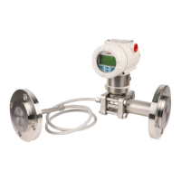
Provides an overview of the AW400 Monitor/Controller family and its types.

Technical Specifications

Display, Power, and Mounting

Covers the LCD display, power supply requirements, and mounting options for the AW400.

Outputs, Alarms, and Ranges

Specifies analog/digital outputs, alarm settings, and measurement ranges for AW400 parameters.

Measure Sensitivity and Environmental Limits

Accuracy and Response Time

Specifies the accuracy, response time, and microprocessor scan cycle of the transmitter.

Hardware Structure Overview

Instrument Operating Block Diagram

Installation Guide

Dimensions and Mounting

Illustrates the physical dimensions and mounting considerations for the AW400.

Mounting Options

Wall Mounting Instructions

Provides detailed instructions and diagrams for wall mounting the AW400 unit.

Pipe Mounting Instructions

Location Requirements

Electrical Connections Guide

Power Supply PC Board Setup

Explains the power supply connection and jumper settings for voltage selection.

Power Supply Cable and Installation

Digital I/O Board Details

Digital Outputs and Relays

Describes the seven relays for digital outputs and their specifications.

Digital Inputs

Analog Input/Output PC Board

Serial Communication and Cable Glands

Set-up and Configuration Menu

Keyboard Functionality

Details the primary and secondary functions of each key on the AW400 interface.

Display Information

Channel Definition Procedure

Set-up Menu Overview

Configuration Parameters

Lists and explains parameters for language, password, serial link, cleaning, and temperature.

Configuration Menu Flowchart

Cleaning Functionality

Instrument Test Procedures

Digital and Analog I/O Tests

Explains how to verify digital input/output and analog I/O signal functionality.

Analog I/O Test Details

Electrical Calibration Notes

Output Setting Configuration

Output Zero and Span Settings

Allows setting current output values (0-20 or 4-20 mA), zero, and full scale.

Output Signal Hardware Modification

Alarms Configuration

Alarm Levels and Dead Band

Enables user to set high/low alarm levels and dead band for each channel.

Alarm Setting Menu

Functionality Overview

Transmitter (AW401) Functionality

Describes digital inputs, digital outputs, and analog output for the transmitter.

Controller (AW402) Functionality

Controller Parameters

Lists and describes general parameters for controller strategies.

Controller Parameters: Feed Forward

Controller Parameters: Sampling/Flow Pacing

Controller Parameters: pH/ORP Control

Controller Parameters: Contact Output

PID Parameters Explained

Defines Proportional Band (PB), Integral Action (TR), and Derivative Action (TD) for PID control.

Feed Forward Configuration Details

Sampling and Flow Pacing Controller Details

Error Squared Controller for pH

Contacts Output Controller Details

Standard Controller Operation

Standard Controller Display

Describes the values displayed by the standard controller, including process variable and set-point.

Standard Controller Output Assignments

Analog Output Assignment

Details how analog output signals are assigned based on controller configuration and channels.

Standard Controller Digital Output Assignment

Calibration Procedures Overview

Calibration Menu and Defaults

Describes the calibration menu, dual point calibration, and default values.

pH Sensor Calibration

Double Point pH Calibration

Provides step-by-step instructions for calibrating pH sensors using two buffer solutions.

Single Point pH Calibration (S.P.C.)

ORP Sensor Calibration

ORP Calibration: Negative Values

ORP Calibration: Positive Values

Chlorine/Chlorine Dioxide/Ozone Calibration

Start Up Procedures

Preliminary Operations Checklist

Lists essential checks before powering up the transmitter for the first time.

Personalization of Parameters

Controller PID Tuning

Maintenance Operations

Periodical Operations Overview

Highlights sensor cleaning and periodic checks for sensitivity and calibration.

Error Messages and Troubleshooting

Operation Messages

Lists messages displayed during normal operation to indicate instrument status.

Error Messages Identification

Serial Communication Standards

Communication Modes and Settings

Describes RS232 and RS422/485 interfaces, modes, and transmission speed settings.

Communication Protocol Definition

Message Types and Commands

Communication Transaction Examples

Transaction A Example

Illustrates a host request for data and the AW400 response.

Transaction B Example

Shows host sending data and AW400 response/acknowledgement.

Serial Link Signal Connection

Data-link Terminator Configuration

AW400 Memory Map Overview

Appendices

EC Declaration of Conformity

States compliance with harmonised generic rules for the CE Mark.

Products and Customer Support

ABB Products Overview

Lists product categories and industries served by ABB automation systems.

Customer Support Services

Details after-sales service and contact information for ABB support centers.

Client Warranty Information

Outlines conditions and documentation required for warranty claims.

Related product manuals