AZ10 OXYGEN ANALYZER | COMBUSTION GAS ANALYSIS | OI/AZ10-EN REV. A
11
Threaded NPT and BSP mountings
WARNING
Failure to observe this warning will result in serious injury.
Before fitting the probe, ensure that the boiler is off and the
flue is cool enough to touch.
If hot process gases are flowing through the flue when the
probe intake tube is inserted, it will direct those gases
toward the operator.
Notes
• The probe can be supplied with either a 2 in NPT or a 2 in BSP
mounting option.
• The gasket joints must be gas tight otherwise errors in the
O readings will occur.
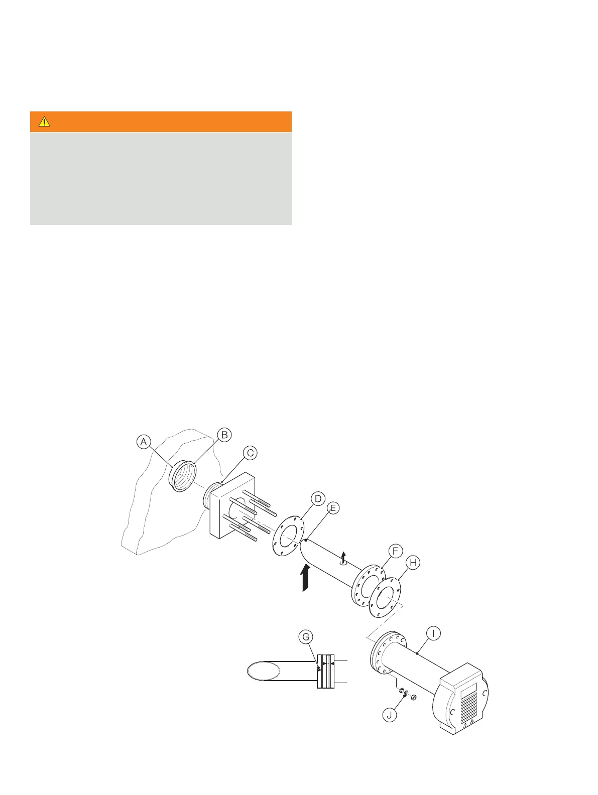
Referring to Figure 8:
1 A in the
flue wall.
2 Weld a 2 in NPT or 2 in BSP female threaded boss B
3 Apply high temperature jointing compound to the threads
C of the probe mount adaptor and screw the adaptor into
the boss.
4 Locate a gasket D
see Notes, left.
5 Insert the probe intake tube E through the adaptor,
ensuring that the open side of the intake tube tip faces into
Figure 7, page 10 and Warning
6 Align the bolt holes F in the probe intake tube flange with
the studs on the adaptor ensuring that the open side of the
intake tube tip continues to face into the gas flow.
An arrow
G is stamped on the tube flange to assist with
orientation.
7 Locate a gasket H
see Notes, left.
8 Fit the probe body I over the studs on the adaptor
ensuring Company name is uppermost.
9
washers
J.
Figure 8 Standard (2 in NPT) and optional (2 in BSP) mountings
Gas flow
Exit