16 AZ10 OXYGEN ANALYZER | COMBUSTION GAS ANALYSIS | OI/AZ10-EN REV. A
7 Electrical connections
WARNING
Bodily injury.
• The transmitter is not fitted with a switch therefore a
disconnecting device such as a switch or circuit breaker
conforming to local safety standards must be fitted to the
final installation. It must be fitted in close proximity to
the instrument within easy reach of the operator and
must be marked clearly as the disconnection device for
the transmitter.
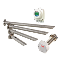
• The probe must be bonded to local earth using the
Figure 11.
•
accordance with relevant national and local standards.
• Remove all power from supply, relay and any powered
control circuits and high common mode voltages before
accessing or making any connections.
• The AZ10 cable carries the screened signal wires and the
not use alternative wires.
• The equipment conforms to Installation Category II of
• All connections to secondary circuits must have basic
insulation.
• After installation, there must be no access to live parts,
for example, terminals.
• Terminals for external circuits are for use only with
equipment with no accessible live parts.
• If the equipment is used in a manner not specified by the
Company, the protection provided by the equipment may
be impaired.
• All equipment connected to the transmitter’s terminals
Figure 11 External earth connection
NOTICE
Earth bonding between the probe and transmitter is
required to ensure effective EMC compliance. Min. 4mm
cable should be used.
CAUTION
• Make connections only as shown.
• Maintain Environmental Protection at all times.
• Ensure the seal and mating surfaces are clean to maintain
environmental rating.
• Ensure cable glands are tightened after wiring.
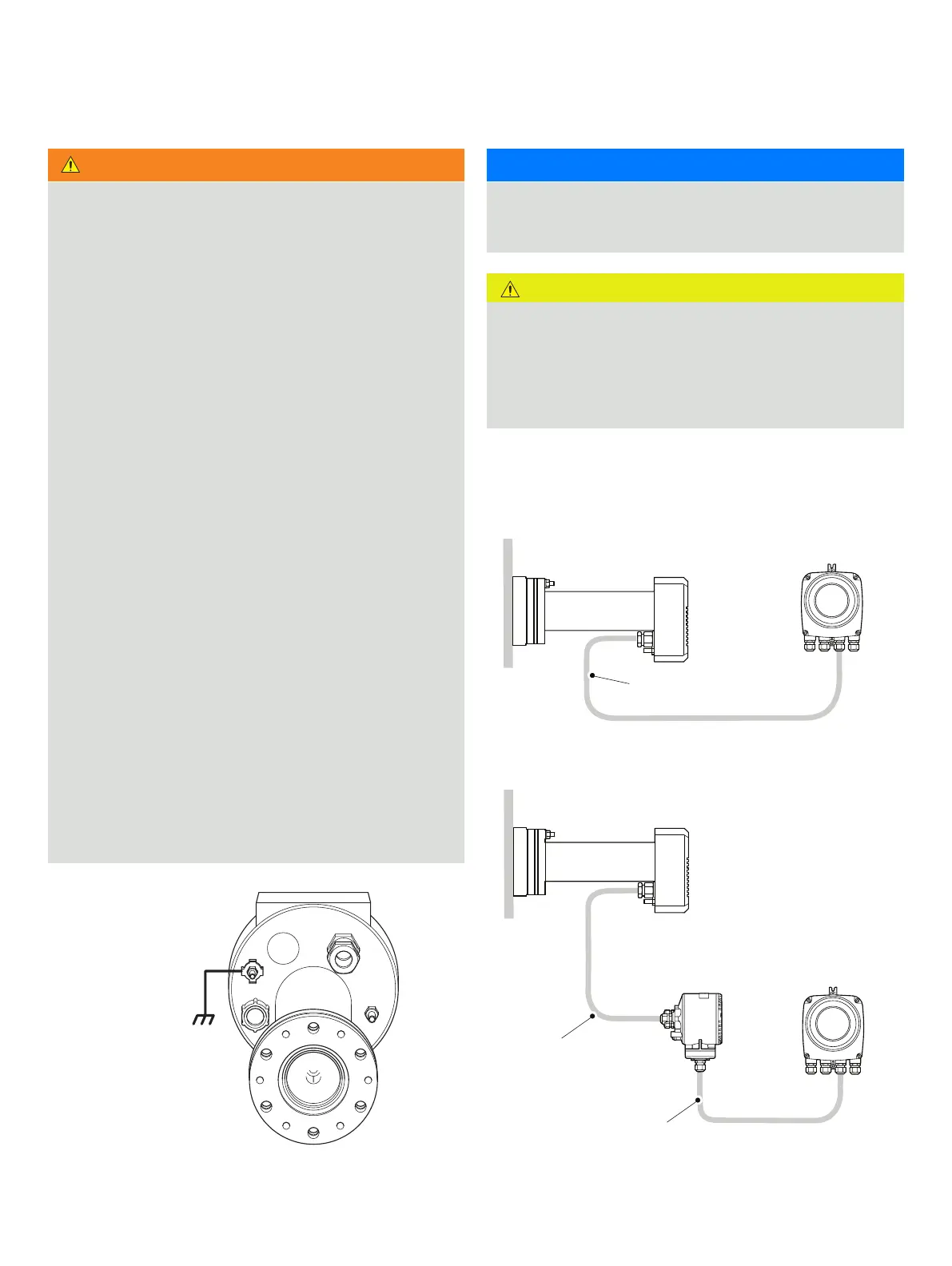
Cable entries
Figure 12 Cable entries
External
see Notice
Non-AutoCal system
AZ10 transmitter
AZ10 probe
Probe to transmitter
Probe to AutoCal unit
AutoCal unit to transmitter
AZ10 probe
AZ10 AutoCal unit
AZ10 transmitter
AutoCal system
probe to AutoCal unit + AutoCal unit to