AZ10 OXYGEN ANALYZER | COMBUSTION GAS ANALYSIS | OI/AZ10-EN REV. A
7
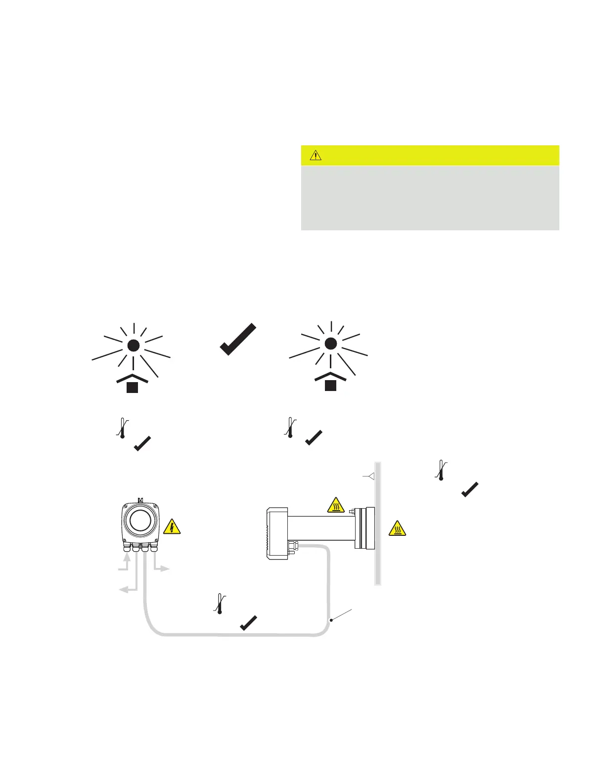
Siting
Select a position where the intake is located in the main gas
stream. Gas temperature must be in the range 20 to 800 °C
Avoid positions where obstructions or bends prevent
Avoid positions where vibration levels induced by other plant
could result in mechanical failure of the probe.
To prevent acid dew-point corrosion, the probe mounting
flange and body must be thermally lagged if the temperature of
when the process is operating.
Maintain the probe terminal head temperature within the
CAUTION
Do not exceed the probe terminal head maximum operating
temperature. The probe must be sited in an area where:
• radiated heat from the process does not cause the
maximum temperature to be exceeded
Probe dimensions are shown in Figure 3, page 8. A clearance
necessary to enable installation or removal.
Siting overview
the transmitter can supply fixed pressure compensation.
Figure 2 Probe and transmitter temperature/environmental limits and power input/output supplies
IP66 (NEMA 4)
IP66 (NEMA 4X)
AZ10 probe
Process
AZ10 transmitter*
Mains supply
Relays
Output signals
800 °C
20 mm or
½ in NPT gland
Surface 400 °C