AZ10 OXYGEN ANALYZER | COMBUSTION GAS ANALYSIS | OI/AZ10-EN REV. A
17
Probe connections, general
WARNING
Bodily injury.
• Before making any connections, ensure that the power
supply, any high voltage-operated control circuits and
high common mode voltages are switched off.
Perform the procedures detailed below.
A 4 mm earth bonding point is provided on the back of the
Figure 11.
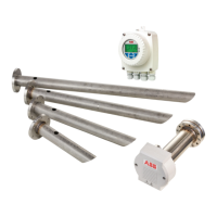
Access to probe terminals
Referring to Figure 13:
1 Release 2 captive screws A securing terminal cover B
and remove the terminal cover.
Figure 13 Removing probe terminal cover
Preparing the cable(s)
systems before connections can be made.
Cable requirements:
• one length of 14-core cable is required to connect
• two lengths of 14-core cable are required to connect
combined length 100 m
Refer to the following pages for connection requirements:
• page 19
• page 21 and page 22 for AutoCal systems
Cable glands
NOTICE
The special EMC cable gland supplied with the probe/
transmitter can be replaced by any ½ in NPT or ½ in BSP,
EMC metal gland that forms a watertight seal on the outer
sheath of the cable and an electrical contact to the braided
copper shield.
The gland must form a good electrical contact with the
probe for grounding purposes and form a NEMA 4X
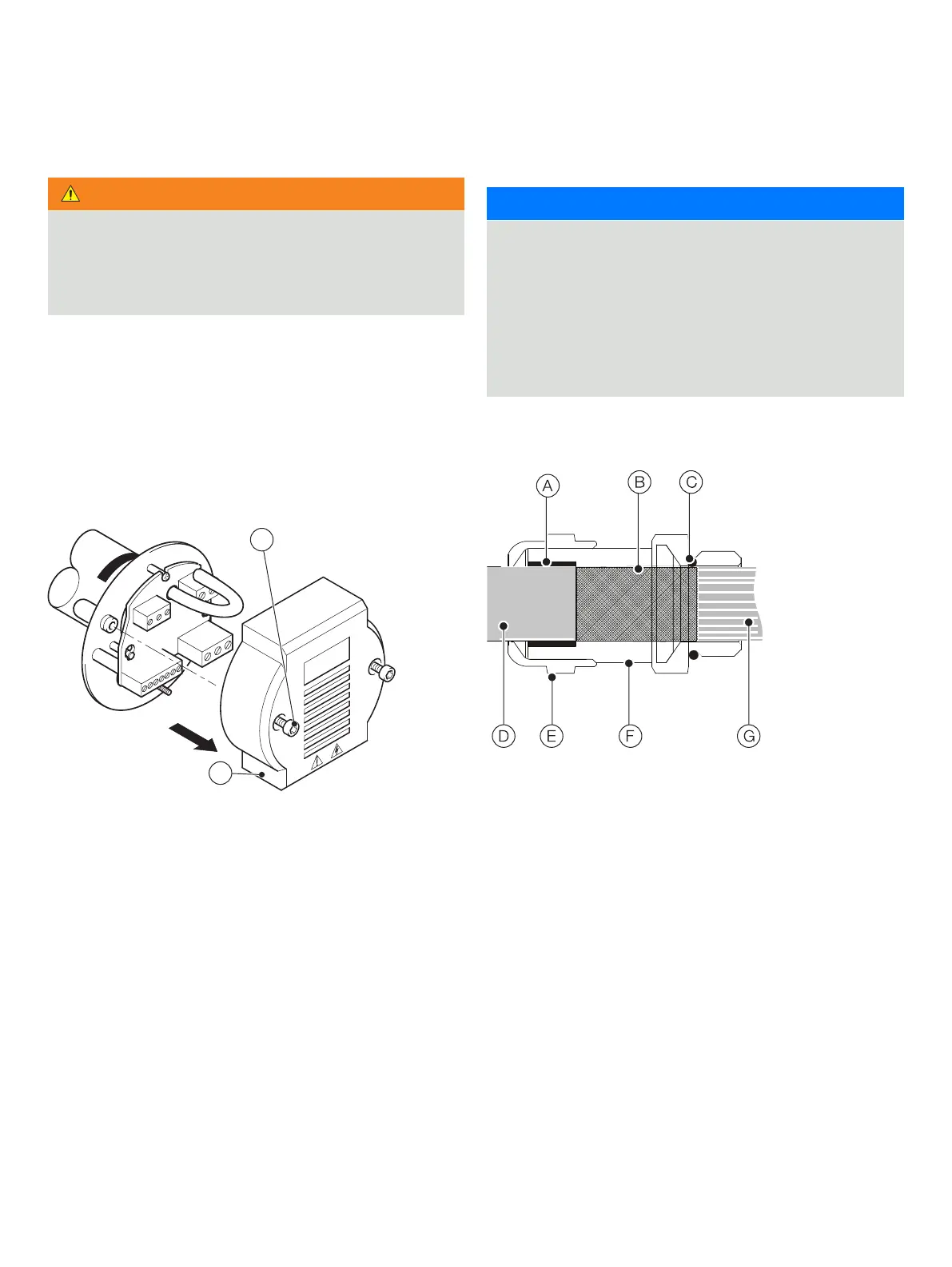
EMC cable gland
Locate cable glands before preparing cable.
A Rubber environmental seal
B Braided copper cable shield
, page 18
C
D Cable sheath
, page 18
E Gland outer nut
F Gland clamping sleeve
G Cable wires to terminals
, page 18
Figure 14 EMC Cable gland shown fitted to cable
B