AZ10 OXYGEN ANALYZER | COMBUSTION GAS ANALYSIS | OI/AZ10-EN REV. A
19
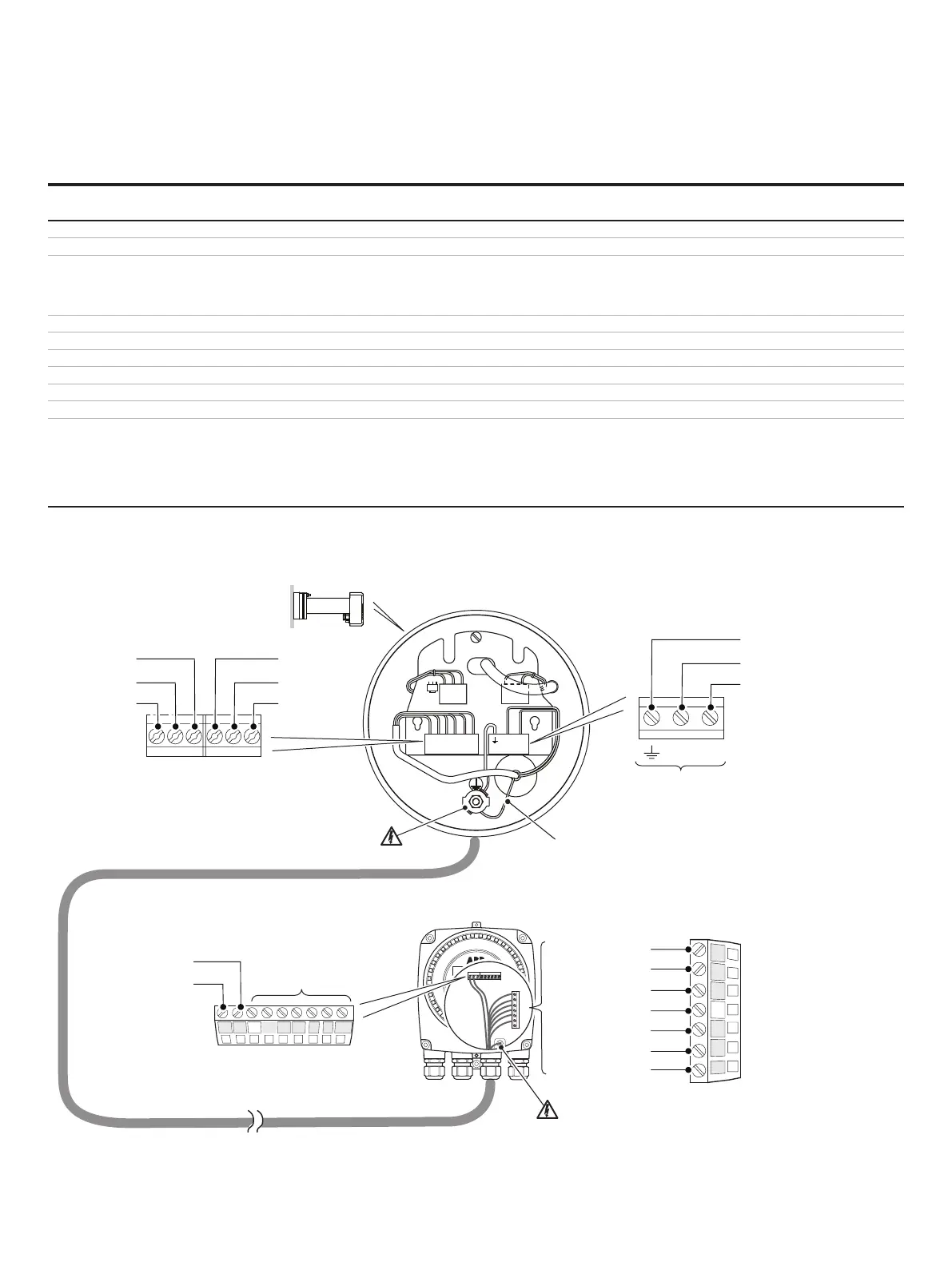
Electrical connections – non-AutoCal systems/AZ10 probe to AZ10 transmitter
Wire
color
Transmitter connection/
terminal color
Probe
terminal
Connection
type
Brown
Blue
internal earth stud and connect an internal
earth wire from probe earth terminal to probe
internal earth stud at probe
NOT USED)
transmitter internal earth stud only
Internal earth stud
connect at probe earth stud
and transmitter earth stud only
White White
Green Green TC+ T/C +
Grey Grey ACJC ACJC
Violet Violet ACJC ACJC
Black Black
Red Red Cell +
White/Yellow
White/Black
White/Orange
White/Green
White/Red
White/Blue
Not fitted Not applicable
Table 1 Cable requirements – non-AutoCal systems/AZ10 probe to AZ10 transmitter
Figure 16 Electrical connections – AZ10 probe to AZ10 transmitter (non-AutoCal systems)
VIOLET
BLACK
RED
WHITE
CELL
–+–+
GREY
GREEN
T/C
ACJC
CELL
T/C
–
+
+
R
W
BL
BLUE
BROWN
GREEN
H1
CLR
CLR
H2
H1 H2
12
9
8
7
6
5
4
3
AZ10 probe
AZ10 transmitter
Connect Screen 1 and 2 drains from
14-core cable to internal earth stud only
Connect screen 1 and 2 drains from 14-core cable
do not connect the drains to the transmitter
SCN connector or the transmitter external earth
Probe heater connections and internal
earth connection wire from earth stud
after being passed into sensor head
AutoCal terminals
at transmitter
not used
not used
Heater connections
at transmitter