4
…2 ELECTRICAL INSTALLATION
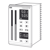
2.4 Pull-up and Pull-down Resistors – Figs. 2.1 and 2.2
To prevent false triggering of slaves when the master (host computer) is inactive, pull-up and pull-
down resistors must be fitted to the RS422/485 interface in the host computer – see Figs. 2.1 and 2.2.
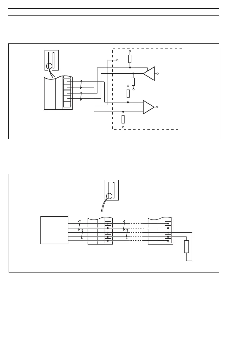
Fig. 2.3 Connecting Multiple Slaves
Fig. 2.2 Pull-up and Pull-down Resistors (Four-wire Operation)
Host Computer
+5V
0V
'A
'B
1.8kΩ
Pull-down
Resistor
1.8kΩ Pull-up
Resistor
0V
+5V
0V
'A
'B
1.8kΩ
Pull-down Resistor
1.8kΩ
Pull-up
Resistor
Rx+
Rx–
Tx–
Tx+
C
32
33
34
35
36
C500
First Slave Last Slave
Tx+
Tx-
Rx+
Rx-
C
120Ω
Termination Resistor
(External)
Master
Rx+
Rx–
Tx+
Tx–
GND
Tx+
Tx–
Rx+
Rx–
C
32
33
34
35
36
C500
Host
Computer
32
33
34
35
36
2.5 Termination Resistor – Fig. 2.3
For long transmission lines, a 120Ω termination resistor must be fitted to the last slave in the chain
– see Fig. 2.3.