27
− Auxiliary voltage input (X99).
− External measurement channels (X54, X60, X65).
− Voltage measurement (X51, X52, X53 and X55, X56, X57).
− Cooling fans (X41 … X44) if existing.
− Snubber resistor (X30, X31).
− Gate leads (X15, X17).
− Temperature sensor (X22).
− Current transformers (X3, X4, X5).
13. Reconnect the flat cables at the SDCS-CON-H (X14, XC12, XS13), the cable at X38 and re-hinge the
electronic tray.
14. Reconnect the grounding / holding screws at the electronic tray.
15. Reconnect all I/O plugs at the SDCS-CON-H.
16. Reinstall all plug in options (do not forget the screws), the design cover and the control panel.
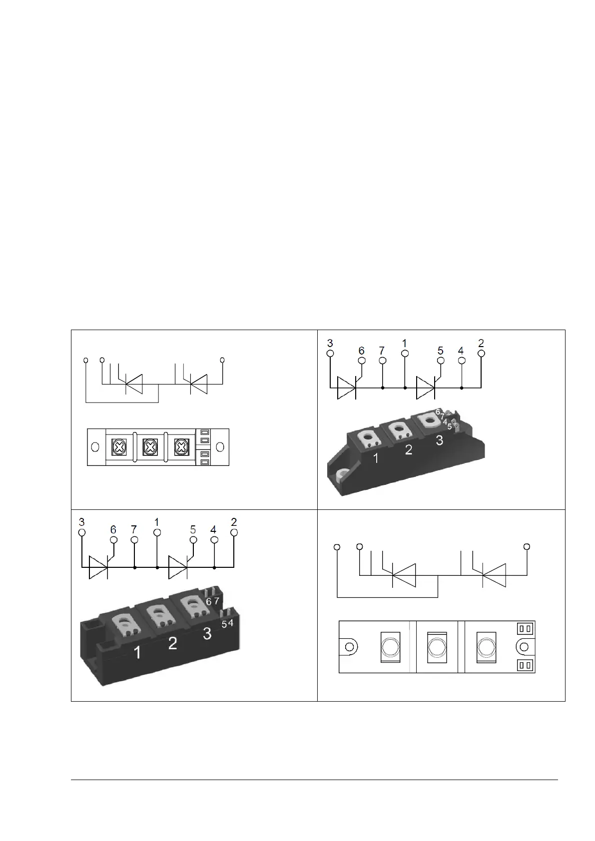
Thyristor module terminals
The next figures show the terminals of all used thyristor modules. The terminal description is also stamped or
marked by a sticker on all thyristor modules.
For all firing pulse cables is valid:
− Yellow is gate lead.
− Red is cathode lead.
Exchange thyristors sizes T1 … T4
3ADW000449R0101 DCT880 Service Manual e a