39
17. Remove the gate leads from the faulty thyristor module and mark the connectors clearly.
Remove only as many parts as needed around the faulty thyristor module.
18. Remove the faulty thyristor module and mark it clearly as defective.
Install new thyristor modules
1. Ensure that the new thyristor module is of the correct type (see Appendix A of this manual).
2. Remove old heat-conducting compound (grease) from the heat sink. Clean the mounting surfaces (heat
sink and thyristor module) with an appropriate solvent (e.g. ethanol) by means of tissue paper. When the
heat sink is clean, spread out the heat-conducting compound with a rubber spatula or by hand.
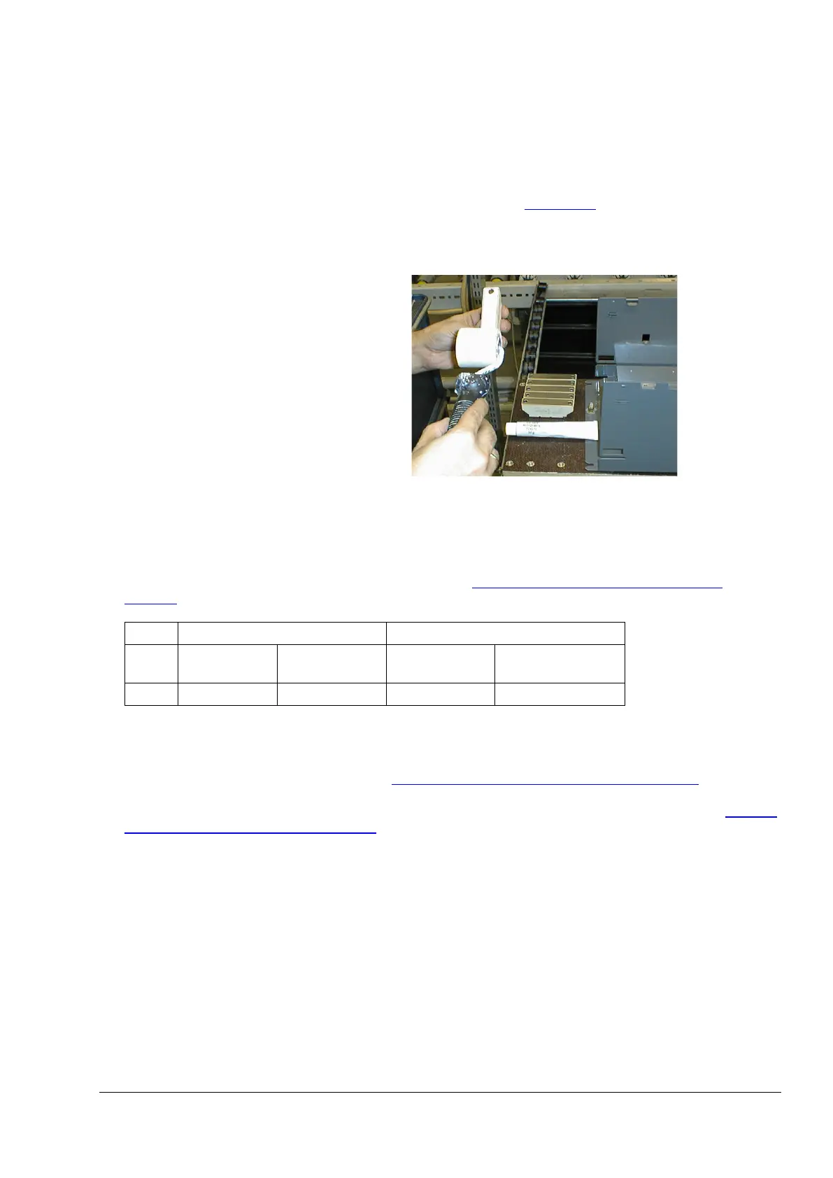
3. Apply a thin layer of heat conducting
compound to the new thyristor module.
4. Spread the heat-conducting compound evenly by moving the thyristor module forward and backward on
the heat sink.
5. Tighten all clamping screws by hand until the screw heads touch the bottom of the thyristor module. Then
pre-torque the screws to 2.0 Nm.
Note:
If the thyristor module is mounted by means of four screws, tighten the screws crosswise.
6. Tighten the screws to nominal torque according to table
Nominal mounting torque for T5 thyristor
modules.
Unit Thyristor modules Nominal mounting torque
Size Size (width) Type Electrical
Thyristor module
T5 60 mm block MT3-540, 595 12 Nm 6 Nm
7. Reconnect all gate leads to the thyristor module.
8. Perform an OHM test to make sure the thyristor is ok.
9. Reinstall the busbar arrangement at the bottom together with the U2, V2 and W2 busbars. Make sure, the
correct torque is applied according to table Nominal mounting torque for T5 thyristor modules
.
10. Reinstall the six fuses.
11. Reinstall the U1, V1 and W1 busbars. Make sure, the correct torque is applied according to table
Nominal
mounting torque for T5 thyristor modules.
12. Reinstall the plastic cover and the SDCS-PIN-H board.
13. Reconnect all cables and plugs at the SDCS-PIN-H:
− Auxiliary voltage input (X99).
− External measurement channels (X54, X60, X65).
− Voltage measurement (X51, X52, X53 and X55, X56, X57).
− Snubber resistor (X30, X31).
− Gate leads (X15, X17).
− Temperature sensor (X22).
− Current transformers (X3, X4, X5).
14. Reconnect the flat cables at the SDCS-CON-H (X14, XC12, XS13), the cable at X38 and re-hinge the
electronic tray.
15. Reconnect the grounding / holding screws at the electronic tray.
16. Reconnect all I/O plugs at the SDCS-CON-H.
17. Reinstall all plug in options (do not forget the screws), the design cover and the control panel.
Exchange thyristors size T5
3ADW000449R0101 DCT880 Service Manual e a