Do you have a question about the ABB DCT880 and is the answer not in the manual?
Describes the purpose, contents, and intended use of the manual's safety section.
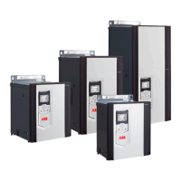
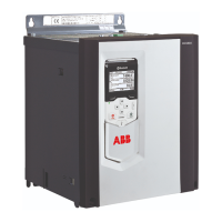
Specifies the product range for which the safety instructions are valid.
Explains the meaning of different warning and note symbols used in the manual.
Critical safety warnings for qualified electricians performing installation and maintenance.
Instructions for proper grounding of the thyristor power controller for safety and EMC.
Safety warnings regarding handling ESD-sensitive printed circuit boards.
Notes on handling the thyristor power controller to avoid damage and injury.
Safety warnings for operating the thyristor power controller and its connected equipment.
Safety instructions related to mains disconnection, fuses, and emergency stop buttons.
Clarifies the intended use and responsibilities for non-industrial installations.
Outlines the structure and content of the service manual.
Identifies the intended audience for this manual and their required knowledge.
Provides guidelines for storing and transporting the unit.
Explains the purpose and information found on the unit's name plate.
Details the meaning of the different parts of the thyristor power controller's type code.
Provides voltage and current ratings for different unit configurations.
Lists current, power, and loss ratings for three-leg anti-parallel units.
Lists current, power, and loss ratings for three-leg anti-parallel 690V units.
Details current ratings based on supply frequency, ambient temperature, and altitude.
Lists mandatory tools and software for commissioning and fault tracing.
Specifies mandatory software for commissioning and fault tracing.
Lists essential additional tools required for fault tracing.
Lists mandatory tools for cleaning.
Explains methods to identify thyristor problems, including blown fuses.
Guides on using an oscilloscope to check output current for phase angle control.
Mentions using firmware for thyristor diagnosis (under construction).
Provides steps to identify and exchange faulty thyristors in T1-T4 units without +S500.
Describes how to check for blown external fuses using a multimeter.
Explains how to test thyristors for short circuits using a multimeter.
Details finding faulty thyristors in T5 units without +S500, including internal fuses.
Describes checking for blown internal fuses in T5 units.
Explains testing thyristors in T5 units for short circuits.
Details finding faulty thyristors in T1-T4 units with +S500, including internal fuses.
Describes checking for blown internal fuses in T1-T4 units with +S500.
Explains testing thyristors in T1-T4 units with +S500 for short circuits.
Provides general guidelines for handling thyristor modules, busbars, and fuses.
Instructions for installing thyristor modules in T1-T4 units, focusing on heat sink and connector conductivity.
Lists special tools and materials needed for thyristor module exchange.
Steps to remove the control panel, design cover, and extension modules.
Steps to disconnect I/O plugs and remove grounding/holding screws for the electronic tray.
Instructions for unhinging the electronic tray and unplugging flat cables.
Details removing auxiliary voltage input and external measurement channels.
Guides on removing voltage measurement connections and cooling fans.
Instructions for removing snubber resistors and gate leads.
Steps to remove temperature sensors, current transformers, and the SDCS-PIN-H board.
Steps to remove gate leads and busbars/fuses for module access.
Guides on selecting the correct thyristor module type and applying thermal compound.
Instructions for tightening screws to the correct torque for module mounting.
Steps for reinstalling current transformers, busbars, and gate leads.
Shows terminal configurations for various thyristor modules (SKKT, MCC, etc.).
Provides detailed diagrams and dimensions for specific thyristor modules.
Instructions for installing thyristor modules in T5 units, focusing on heat sink and connector conductivity.
Lists special tools and materials needed for thyristor module exchange in T5 units.
Steps to remove the control panel, design cover, and extension modules for T5 units.
Steps to disconnect I/O plugs and remove grounding/holding screws for the electronic tray in T5 units.
Instructions for unhinging the electronic tray and unplugging flat cables for T5 units.
Details removing auxiliary voltage input and external measurement channels for T5 units.
Guides on removing voltage measurement connections for T5 units.
Instructions for removing snubber resistors and gate leads for T5 units.
Steps to remove temperature sensors, current transformers, and holding screws for T5 units.
Steps to remove the plastic cover and SDCS-PIN-H for T5 units.
Instructions for removing screws from busbars and fuses for T5 units.
Steps to remove busbars from T5 units.
Instructions for removing fuses from T5 units.
Steps to loosen bottom screws for busbar removal in T5 units.
Instructions for removing screws holding U2, V2, W2 busbars in T5 units.
Steps to remove U2, V2, W2 busbars and the bottom busbar arrangement in T5 units.
Guides on checking thyristors after component removal in T5 units.
Guides on selecting the correct thyristor module type and applying thermal compound for T5 units.
Instructions for tightening screws to the correct torque for T5 module mounting.
Steps for reconnecting gate leads, busbars, and fuses for T5 units.
Shows the physical location of thyristor modules in T5 units.
Shows terminal descriptions and gate/cathode lead identification for T5 thyristor modules.
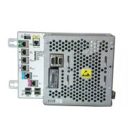
States that SDCS-CON-H board exchange is similar across all unit sizes.
Lists necessary tools for exchanging the SDCS-CON-H board.
Outlines the steps for exchanging the SDCS-CON-H board.
Instructions to record the unit type code before board exchange.
Steps to remove the control panel and design cover for tray exchange.
Details removing and transferring the memory unit containing firmware and parameters.
Guides on removing F-type extension modules from the electronic tray.
Instructions for disconnecting all I/O plugs from the SDCS-CON-H.
Steps to remove grounding and holding screws for the electronic tray.
Instructions for unhinging and removing the electronic tray with SDCS-CON-H.
Refers to setting the type code after the board exchange.
Safety warning and overview for exchanging cooling fans in T1-T3 units (two fans).
Steps to remove the control panel and design cover to access the fan.
Instructions for removing screws securing the fan arrangement.
Guides on moving the fan assembly to allow access for fan removal.
Instructions for disconnecting fan plugs from the SDCS-PIN-H.
Steps to remove screws holding the fan in place.
Safety warning and overview for exchanging cooling fans in T3 units (four fans).
Steps to remove the control panel and design cover to access the fans.
Instructions for removing screws securing the fan arrangement.
Guides on moving the fan assembly to allow access for fan removal.
Instructions for disconnecting fan plugs from the SDCS-PIN-H.
Steps to remove screws holding the fan in place.
Safety warning and overview for exchanging cooling fans in T4 units.
Steps to remove the control panel, design cover, and fan connection plug.
Instructions for removing screws securing the fan arrangement.
Guides on removing holding plugs for fan assembly.
Instructions for moving the fan assembly to allow access for fan removal.
Steps to remove screws holding the fan in place.
Instructions for removing Faston plugs and the fan.
Safety warning and overview for exchanging cooling fans in T5 units.
Steps to remove screws from the bottom of the fan arrangement.
Lists necessary tools for exchanging internal semiconductor fuses.
Safety warning before starting fuse exchange.
Instructions on how to find blown semiconductor fuses using a multimeter.
Steps to remove the control panel and design cover for fuse access.
Guides on removing F-type extension modules for fuse access.
Instructions for disconnecting I/O plugs from the SDCS-CON-H for fuse access.
Steps to remove grounding and holding screws for the electronic tray.
Instructions for unhinging and removing the electronic tray with SDCS-CON-H.
Details removing auxiliary voltage input and external measurement channels.
Guides on removing voltage measurement connections and cooling fans.
Instructions for removing snubber resistors and gate leads.
Steps to remove temperature sensors and current transformers.
Instructions for removing the SDCS-PIN-H board.
Steps to remove broken semiconductor fuses.
Guides on installing new fuses, performing OHM tests, and reinstalling components.
Lists necessary tools for exchanging internal semiconductor fuses in T5 units.
Safety warning before starting fuse exchange in T5 units.
Instructions on finding blown fuses using a multimeter in T5 units.
Steps to remove the control panel and design cover for fuse access in T5 units.
Guides on removing F-type extension modules for fuse access in T5 units.
Instructions for disconnecting I/O plugs from the SDCS-CON-H for fuse access in T5 units.
Steps to remove grounding and holding screws for the electronic tray in T5 units.
Instructions for unhinging and removing the electronic tray with SDCS-CON-H in T5 units.
Details removing auxiliary voltage input and external measurement channels.
Guides on removing voltage measurement connections.
Instructions for removing snubber resistors and gate leads.
Steps to remove temperature sensors, current transformers, and holding screws for T5 units.
Steps to remove the plastic cover and SDCS-PIN-H for T5 units.
Instructions for removing screws from busbars and fuses for T5 units.
Steps to remove busbars from T5 units.
Instructions for removing fuses from T5 units.
Guides on selecting correct fuses, performing OHM tests, and reinstalling components.
Steps for reinstalling busbars and reconnecting cables and plugs.
States that this section describes downloading firmware into the SDCS-CON-H.
Instructions for installing the Drive loader software.
Advises on backing up parameters and application programs before firmware download.
Lists prerequisites and steps for performing the firmware download.
Steps for selecting the firmware file within the Drive loader.
Guides on selecting the device type (ACS880) in the Drive loader.
Instructions on how to find and select the correct COM port for the connection.
Detailed steps to locate the correct COM port via Control Panel and Device Manager.
Explains how to find the COM port under Device Functions.
Guides on selecting the COM port and initiating the download process.
Instructs to confirm the download process after selection.
Notifies the user about the download duration and potential risks.
Final step to close the Drive loader application.
Advises to verify the installed firmware version.
Explains the factory preset and write-protected type code and its function.
Instructions on how to change the unit's type code using the control panel.
Details the structure and components of the DCT880 basic type code.
Emphasizes following safety instructions before any maintenance.
Warns about ESD sensitive components and the need for an ESD kit.
Provides guidelines for handling ESD sensitive boards and protective packaging.
Recommends regular inspection based on the maintenance schedule for optimal performance.
Presents a detailed schedule for preventive maintenance tasks over years.
Explains the symbols used in the maintenance schedule (R, I, P, (R)).
Lists specific actions for annual preventive maintenance, including fan and filter checks.
Guides on cleaning heatsinks and checking for dust, corrosion, and temperature issues.
Details additional actions for 3-year preventive maintenance, like checking terminals and contactors.
Lists actions for 6-year maintenance, including fan replacement and checking flat cables.
Explains component aging effects like vibration and increased temperature.
Details actions for 9-year maintenance, including replacing the SDCS-PIN-H board and flat cables.
Lists consequences of electronic card aging, like device damage and shutdowns.
Describes issues caused by flat cable aging, such as contact problems and insulation breaks.
Provides a checklist template for performing and recording preventive maintenance.
Checklist items related to checking the environment, documentation, and spare parts.
Checklist items for cleaning and inspecting components without voltage.
Checklist items for maintenance performed with the supply voltage applied.
Checklist items for preventive replacement of flat cables, boards, and fans.
Field for adding specific notes or observations during inspection.
Lists spare parts for DCT880 thyristor power controllers of size T1.
Lists spare parts for DCT880 thyristor power controllers of size T2.
Lists spare parts for DCT880 thyristor power controllers of size T3.
Lists spare parts for DCT880 thyristor power controllers of size T4.
Lists spare parts for DCT880 thyristor power controllers of size T5.
Describes the compact DCS550-S modules for machinery applications.
Describes the versatile DCS800-S modules for process industry.
Describes DCS800-A complete drive solutions.
Describes DCS800-E pre-assembled drive-kits.
Describes DCS800-R digital control-kit for existing powerstacks.
| Brand | ABB |
|---|---|
| Model | DCT880 |
| Category | Controller |
| Language | English |