Modifications reserved
6 Control and monitoring
6.1 Control panel module
ONLY PERSONS TRAINED BY THE MANUFACTURER’S SERVICE
TECHNICIANS OR HIS CERTIFIED SERVICE PARTNERS ARE ALLOWED TO
OPERATE THE CONTROL PANEL WITH CLOSED DOORS. ALL OTHER
INTERVENTIONS ON THE UPS HAVE TO BE PERFORMED BY THE
MANUFACTURER’S SERVICE TECHNICIANS ONLY
The user-friendly control panel is composed of three parts:
• Power management LCD display (PMD);
• Led indicators;
• Keys.
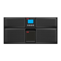
Fig 6.1-1: Control Panel
The 2 x 20 character LCD simplifies communication with the UPS and provides the necessary UPS
monitoring information. The menu-driven LCD enables the user to:
• Access the event register
• Monitor the input and output U, I, F and P
• Check battery runtime
• Perform commands like start-up and shut-down of the UPS, and load transfer from the inverter
to the bypass and vice-versa
• Perform a diagnosis (service mode)
• Carry out adjustments and testing
6.1.1 Status and alarm indication
The mimic diagram serves to indicate the general status of the UPS. The LED indicators show the
power flow status and (in the event of mains failure) load transfer from the inverter to bypass and vice-
versa. The corresponding LED indicators will change color from green (normal) to red (warning).
The LEDs LINE 1 (rectifier) and LINE 2 (bypass) indicate the availability of the mains power supply.
The INVERTER and BYPASS LEDs, if green, indicate which of the two is supplying power to the
critical load. When the battery is supplying the load due to mains failure, the LED indicator BATTERY
will flash.
 Loading...