Do you have a question about the ABB DPA 250 S4 and is the answer not in the manual?
Details about the document, including file name, issue date, and author.
Explanation of symbols used in the manual and their associated safety warnings.
Guidance on keeping and following the manual's important instructions.
Key safety rules and precautions to follow during operation and maintenance.
Declaration of compliance with European directives and relevant standards.
Details on the UPS system nameplate and its identification.
Information on the UPS module nameplate and identification details.
Overview of the DPA 250 S4 UPS system architecture and capabilities.
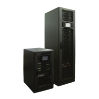
Description of the different DPA 250 S4 UPS frame configurations available.
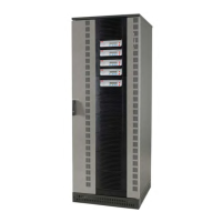
Illustrations and details of UPS frames equipped with a closed door.
Illustrations and details of UPS frames equipped with an open door.
Specifications for the overall dimensions of the UPS frame.
Description of the DPA 250 S4 M50 UPS module, its core engine.
Physical dimensions and specifications for the UPS module.
Details on standalone and parallel UPS system configurations.
Description of how to configure the UPS in a standalone setup.
Explanation of how to configure multiple UPS units in parallel.
Specifics on setting up a parallel UPS system with ring communication.
Overview and functional description of the UPS system's main components.
Single line diagram for single input feed with common batteries.
Single line diagram for dual input feed with common batteries.
Single line diagram for single input feed with separate batteries.
Single line diagram for dual input feed with separate batteries.
Functional descriptions of various terminals and components within the UPS.
Description of the elements used for UPS measurement, control, and monitoring.
Explanation of the double conversion operating mode for load protection.
Details on Xtra-VFI mode for adaptive power capacity and module standby.
Description of the bypass mode operation, where load is supplied from bypass mains.
Explanation of operation when the UPS is running on battery power.
Procedures for using the maintenance bypass switch for service.
Overview of the touch screen graphical display for system monitoring.
How to operate the graphical display for simple UPS operation and configuration.
Identification of ports and indicators on the rear panel of the UPS.
Initial steps for starting up and installing the UPS system.
Description of the main home screen and its access points.
Explanation of the various icons used in the UPS display interface.
How to navigate through the UPS system's menus and screens.
Description of the mimic diagram, showing power flow and system status.
How to select and navigate individual UPS modules for status checks.
Overview of screen measurements, commands, UPS data, and user settings.
Details on the Xtra VFI feature, its statuses, and module rotation.
Description of the UPS module's control panel elements.
Detailed breakdown of the control panel components like LCD and buttons.
Explanation of the sections and features of the LCD display.
Instructions for using the ON/OFF button for startup and shutdown.
Functionality of the control and navigation buttons for menu interaction.
Meaning and interpretation of the various LED status indicators.
Overview of the different menus accessible from the control panel.
Description of the customer interface ports for connectivity and information.
Details on the input dry ports (X3) for digital inputs and outputs.
Information on output dry ports (X2 and X1) for relays and interlock functions.
Details on network interface cards for UPS monitoring and management.
Description of the smart port JD1 for serial PC/laptop connection.
Information on using the USB interface for PC/laptop connectivity.
Guidelines for general maintenance and user responsibilities.
Defines the maintenance tasks that can be performed by the user.
Recommendations for regular preventive maintenance inspections.
Procedure for performing a deep battery test on the UPS.
Guidelines for battery maintenance, proper disposal, and recycling.
Information on how to properly dispose of and recycle UPS equipment.
Guidance for troubleshooting common UPS issues and alarms.
Steps to take when an alarm condition occurs, including silencing and identification.
Overview of menu functions, commands, event logs, and measurements.
Identifying major alarm conditions and their suggested solutions.
Guidelines for packing and safely transporting the UPS system.
Procedures for carefully unpacking the UPS equipment upon receipt.
Step-by-step instructions for unpacking the UPS from standard film packaging.
Instructions for unpacking the UPS from sea freight wooden box packaging.
Recommendations for storing the UPS system and batteries.
Guidelines for storing the UPS system when not in use.
Recommendations for storing batteries to maintain their lifespan and performance.
Specifies the required environmental conditions for UPS installation.
Details on acceptable ambient temperature and humidity levels.
Requirements related to biological factors like mold, fungus, and pests.
Precautions regarding placement near sources of sand or dust.
Considerations for locations with normal levels of chemical contaminants.
Requirements for areas with insignificant vibration and shock.
Recommendations for optimal UPS placement and required clearances.
Guidance on positioning the battery cabinet relative to the UPS.
Instructions on how to securely fix the UPS unit to the floor.
Key considerations and procedures for the electrical installation of the UPS.
Overview of terminal connections for single input feed configurations.
Overview of terminal connections for dual input feed configurations.
Recommendations for electrical protection and cable sizing based on UPS rating.
Block diagram and protection details for single input feed with common battery.
Block diagram and protection details for single input feed with separate batteries.
Block diagram and protection details for dual input feed with common battery.
Block diagram and protection details for dual input feed with separate batteries.
Table specifying terminal labels, cable sizes, torque, and descriptions.
General information and safety precautions for UPS connections.
Details on connecting UPS input power, including mains and earth.
Ensuring safe connections by checking conditions before wiring.
Instructions for connecting the mains input cable for single input feed.
Instructions for connecting mains input cables for dual input feed.
Guidelines for connecting UPS output loads and relevant precautions.
Instructions for connecting the load cable to the UPS output terminal block.
Procedures for connecting multiple UPS units in parallel for increased capacity.
Briefly refers to standalone connection procedures for parallel setups.
Instructions for installing the parallel communication cable between UPS units.
Details on DIP switch and jumper settings for parallel interface configuration.
Step-by-step guide for the initial start-up and commissioning of the UPS.
Checks to perform before powering on the UPS system in parallel.
Procedure for checking the input phase rotation and sequence.
Steps for installing modules and verifying their parameters.
Verifying feedback signals from maintenance bypass (Q1) and output isolator (Q2).
Verifying the status and operation of individual UPS modules.
Procedure for connecting batteries and checking their status.
Steps for connecting the load to the UPS system after commissioning.
Step-by-step instructions for completely shutting down the UPS system.
Procedure for transferring the load from inverter to maintenance bypass.
Procedure for transferring the load back from maintenance bypass to inverter mode.
Procedure for adding or replacing a module in a single-module system.
Steps to safely remove a UPS module from its frame.
Steps to safely insert a new UPS module into its frame.
Procedure for adding or replacing modules in redundant multi-module systems.
Steps to remove a module from a redundant multi-module system frame.
Steps to insert a module into a redundant multi-module system frame.
Procedures for adding/replacing modules in capacity multi-module systems.
Steps to remove a module from a capacity multi-module system frame.
Steps to insert a module into a capacity multi-module system frame.
Instructions for implementing a remote shutdown sequence for the UPS.
Description of the generator ON facility for automatic generator control.
Detailed setup and operation of the Xtra VFI feature.
Configuration of Xtra VFI parameters like Highest Load Step and Redundancy Level.
Overview of the display menus relevant to the Xtra VFI feature.
Details on network interface cards for UPS connectivity and monitoring.
Description of the CS121 basic card for network interfacing.
Details on the CS121 advanced card for connecting sensors and I/O options.
Information on the CS121 Modbus card for network and alarm integration.
Instructions for installing the SNMP network interface board.
Information about the elevation kit for UPS installation.
Details on the battery temperature sensor option and its functions.
Explains the two main functions of the installed battery temperature sensor.
Instructions for installing the battery temperature probe correctly.
Reference to the technical data sheet for detailed specifications.
| Category | UPS |
|---|---|
| Model | DPA 250 S4 |
| Manufacturer | ABB |
| Nominal Output Power | 250 kW |
| Topology | Double Conversion Online |
| Transfer Time | 0 ms |
| Power Rating | 250 kVA |
| Input Voltage | 380/400/415 V (3-phase + N) |
| Output Voltage | 380/400/415 V (3-phase + N) |
| Frequency | 50/60 Hz |
| Harmonic Distortion | <3% THDi at full load |
| Battery Type | Valve-Regulated Lead-Acid (VRLA) |
| Communication Interface | SNMP |
| Operating Temperature | 0 to 40 °C |
| Storage Temperature | -25 to 55 °C |
| Relative Humidity | 0 to 95% non-condensing |
| Standards Compliance | IEC 62040-1, IEC 62040-2 |


