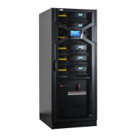
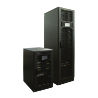
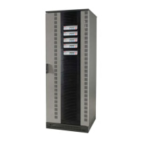
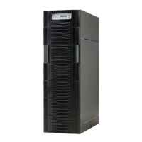
24 DPA 250 S4 50-250 KW OPERATING MANUAL
Section Component Functional Description
Main input terminals (X3)
X3.1 Rectifier input terminal, phase 1
Provides a connection be-
tween the utility supply
and the rectifier input
X3.2 Rectifier input terminal, phase 2
X3.3 Rectifier input terminal, phase 3
X6 - N Neutral terminal
X7 - PE Ground (earth) terminal
Bypass input terminals (X4)
X4.1 Bypass input terminal, phase 1
Provides a connection be-
tween the bypass supply
and UPS bypass input
X4.2 Bypass input terminal, phase 2
X4.3 Bypass input terminal, phase 3
X6 - N Neutral terminal
System output terminals (X2)
X2.1 System output terminal, phase 1
Provide a connection be-
tween the UPS system and
the load
X2.2 System output terminal, phase 2
X2.3 System output terminal, phase 3
X6 - N Neutral terminal
Ground (earth) terminal
Battery terminals (X5)
X501.1
Provides a connection be-
tween the external battery
and the UPS system.
X502.1
X503.1
X504.1
X505.1
X506.1
X501.2 Negative pole (-) of the battery terminal UPS Module 1
X502.2 Negative pole (-) of the battery terminal UPS Module 2
X503.2 Negative pole (-) of the battery terminal UPS Module 3
X504.2 Negative pole (-) of the battery terminal UPS Module 4
X505.2 Negative pole (-) of the battery terminal UPS Module 5
X506.2 Negative pole (-) of the battery terminal UPS Module 6
Battery circuit breaker (Q5)
Q501 Battery circuit breaker UPS module 1, 2P
Battery over current pro-
tective device (MCB).
Q502 Battery circuit breaker UPS module 2, 2P
Q503 Battery circuit breaker UPS module 3, 2P
Q504 Battery circuit breaker UPS module 4, 2P
Q505 Battery circuit breaker UPS module 5, 2P
Q506 Battery circuit breaker UPS modules 6, 2P
3.4.5 Functional description

 Loading...


