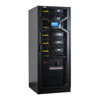
80 DPA 250 S4 50-250 KW OPERATING MANUAL
Q2 ON (Closed) Q2 OFF (Opened)
Display in case of single input feed configuration.
3. The message “UPS now is Master” is now
present in the module event log.
4. By means of the ON/OFF button Load the
module OFF (Confirm with ENTER when
required).
LED indicators status: Module display:
LED INDICATION COLOR SINGLE INPUT FEED CONFIGURATION
Rectifier Green
Bypass
Red (Green if single
input feed)
Load OFF
Battery Flashing Red
5. Repeat the same series of operations with all
other modules present in the parallel installa-
tion. From the last one (below the one just
tested) to the one in the lowest slot of the
first frame).
Do not forget to check the status of LEDs and
display indicators of each module.
10.1.6 Start-up procedure
1. With all modules in the parallel system
Loaded OFF, switch to ON position (close)
the output isolator Q2 of the last frame.
2. In case of “Dual input feed” configuration,
insert the Bypass line fuses in the customer
distribution board.
10.1.5 Modules check
1. Load-On to INVERTER mode the last module
in the parallel installation (The module in the
uppermost slot of the last frame):
• Press the ON/OFF button until the confir-
mation window appears on the display.
• Confirm with ENTER button.
2. Check if the starting sequence is correctly
executed and the UPS switches to INVERTER
mode.
LED indicators status: Module display:
LED INDICATION COLOR SINGLE INPUT FEED CONFIGURATION
Rectifier Green
Bypass
Red (Green if single
input feed)
Load OFF
Battery Flashing Red

 Loading...


