Modifications reserved
16 Wiring and block diagrams for all frames and modules
The customer has to supply the wiring to connect the UPS to the local power source. The installation
inspection and initial start-up of the UPS and extra battery cabinet must be carried out by a qualified
service personnel such as a licensed service engineer from the manufacturer or from an agent
certified by the manufacturer. More details and procedure are mentioned in the user manual.
16.1 Terminal connections overview
Frame type
(T) Compression type
Terminals
(B) Bolted Terminals
Battery
earth
PE
Separate
battery
(+ / N / - )
Common
battery
(+ / N / - )
Input
bypass
3+N
Input
rectifier
3+N+PE
Output
load
3+N+PE
UPScale ST 40
NOT ALLOWED
4 x 16/25 mm
2
(T) 5 x 16/25 mm
2
(T)
UPScale ST 60
4 x 35 mm
2
(T)
4 x 35 mm
2
(T)
+ PE 50 mm
2
(T)
UPScale ST 80
50mm
2
(T)
4x
(3 x 10/16mm
2
) (T)
3 x M6 (B)
3 x 50mm
2
(T)
+ N 50mm
2
(T)
3 x 50mm
2
(T)
+ N 50mm
2
(T)
+ PE 50 mm
2
(T)
UPScale ST 120
1xM10 (B)
6x
(3 x 10/16mm
2
) (T)
3 x 2xM5 (B) or
3 x M10 (B)
4 x 95mm
2
(T)
4 x 95mm
2
(T)
+ PE M10 (T)
UPScale ST 200
1x M10
(B)
5x
(3 x 35mm
2
) (T)
2 modules have
common battery
2x (3x M10) (B)
3x M12 (B)
+ PE 1x M12
4x M12 (B)
+ PE 1x M12
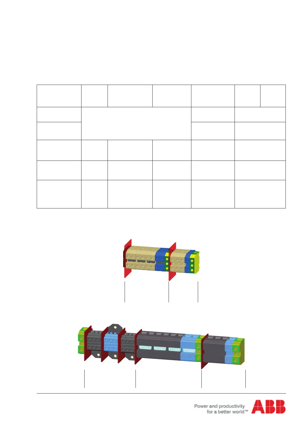
16.2 Terminal connections
Input Output
Battery Input Output