F, V, W S e r i e s
Electromagnetic flowmeters | Full-bore flow sensors 5 Sensor dimensions
38 OI/FEF/FEV/FEW–EN Rev. D
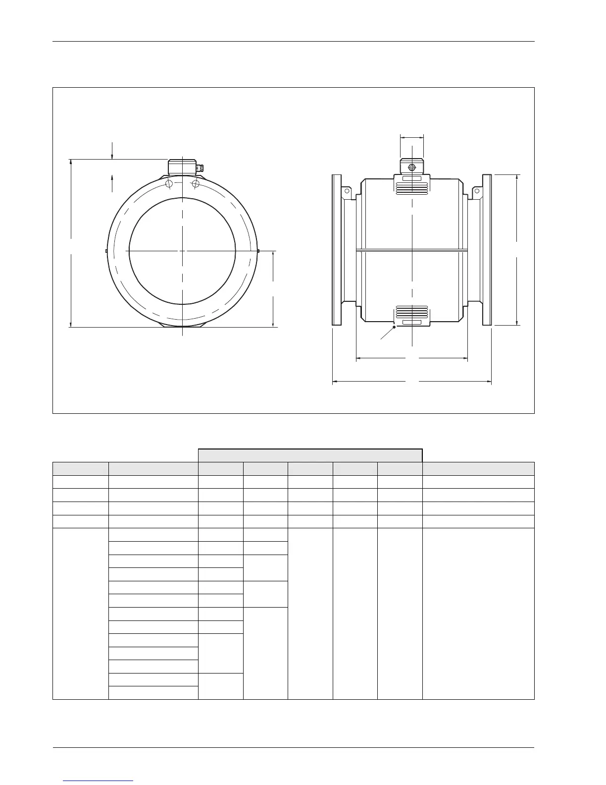
5.5 FEF – DN80 to 600 (3 to 24 in. NB)
Dimensions in mm (in.)
*Dimension C = centre line to base of flowmeter body
Fig. 5.5 DN80 to 600 (3 to 24 in. NB) (FEF)
Dimensions in mm (in.)
DN Mating flange type D L C G A Approx. weight in kg (lb)
DN80 (3 in.) EN1092-1 PN16 200 (7.90) 200 (7.90) 86 (3.40) 258 (10.20) 113 (4.50) 18 (40)
DN100 (4 in.) EN1092-1 PN16 220 (8.70) 250 (9.80) 106 (4.20) 298 (11.70) 140 (5.50) 24 (54)
DN150 (6 in.) EN1092-1 PN16 285 (11.20) 300 (11.80) 138 (5.40) 362 (14.30) 178 (7.00) 38 (84)
DN200 (8 in.) EN1092-1 PN16 340 (13.40) 350 (13.80) 161 (6.30) 408 (16.10) 203 (8.00) 55 (121)
DN250 (10 in.) ASME B16.5 CLASS 150 405 (15.94) 450 (17.72) 215 (8.46) 301 (11.85) 300 (11.81) 88 (194)
ASME B16.5 CLASS 300 445 (17.52) 490 (19.29)
EN1092 -1 PN10 395 (15.55) 450 (17.72)
EN1092 – 1 PN16 405 (15.94)
EN1092 – 1 PN25 425 (16.73) 490 (19.29)
EN1092 – 1 PN40 450 (17.72)
JIS 5K 385 (15.16) 450 (17.72)
JIS 10K 400 (15.75)
AS4087 PN14, PN16 405 (15.94)
AS2129 TABLE C D
AS2129 TABLE E
AS4087 PN21 430 (16.93)
AS2129 TABLE F
Table 5.5 DN80 to 600 (3 to 24 in. NB) (FEF) dimensions / weights
 Loading...