FSM4000 ELECTROMAGNETIC FLOWMETER | DS/FSM4000-EN REV. L
—
… Transmitter
Forward flow/reverse flow measurement
Flow direction is indicated by direction arrows in the display
and over the contact for external signaling. The contact
output can also transmit this information.
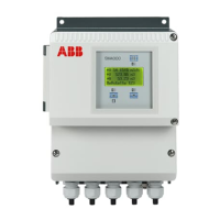
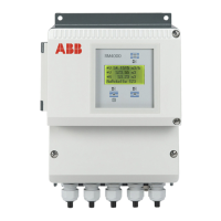
Display
4-line, illuminated graphic display. To improve readability, the
flow information can be displayed on two lines with larger
characters. This allows the individual flowrate and output
values to be displayed. Non-switching measured value
presentation on dot-matrix display with max. 4 × 16
characters. A plaintext diagnostic display opens
automatically when the system detects an error. An alarm
condition can also be signaled via contact output.
Data backup
Via FRAM (Ferroelectric Nonvolatile Random Access Memory),
all data over 10 years old is stored (without power supply) in
the event of shut-off or failure of the line voltage. Additional
security is provided by a serial FRAM installed in the
transmitter and on the external connection board in which
the parameter settings and process information are stored.
This makes it easy to replace a transmitter – without
parameterization – by simply uploading the stored data from
the external FRAM.
Flow totalization
The flow is totalized in engineering units. The limits for the
pulse value can be set, are dynamic and depend on the
measuring range (Qmax) setting as well as the totalizer units
selected. The limits are a min. (0.00016 Hz) and max. pulse
frequency (5 KHz). Totalizer values for the forward and
reverse flow can be displayed simultaneously when
configuring the ‘Display’ parameter.
Parameter configuration
The display supports several languages (German, English,
French, Finnish, Swedish, Italian, Spanish, Dutch or Turkish),
and information can be entered using the three buttons in
the dialog or via a communication interface with a PC, HART®
protocol, PROFIBUS® or FOUNDATION Fieldbus®. The magnet
stick can also be used to configure the flowmeter with the
front door closed. Position the magnet stick over the magnet
icons on the display cover.
Alarm signaling
A max-min alarm can be used with the transmitter. The max.
and min. limit values can be set in the range from 0 to 103 %
of the flow rate. When the flowrate is outside the alarm limits,
an error message is displayed in the upper line and a contact
is triggered. The contact output can also transmit this
information.
Wiring error
Monitoring of magnet coil or electrode circuits for short
circuits or wire breaks.
Isolation of input/output
The current output, pulse output, contact input and contact
output are electrically isolated from the input circuit and
from each other.
Retrofitting
The transmitter with all its functions can also be used with
older model electromagnetic flowmeters. The appropriate
model number must be selected during parameter setting of
the transmitter. It is also possible to use the transmitter with
model 10D1422 flowmeters. A special FRAM (Cs = 100 %,
Cz = 0 %) is required when retrofitting (see ordering
information for the transmitter) and applies for nominal
diameter range DN 3 to DN 1000 (1/10 to 40”) in low voltage
design only.
 Loading...
