Do you have a question about the ABB FSM4000 and is the answer not in the manual?
Structure and meaning of warning signals (DANGER, WARNING, CAUTION, NOTICE).
Specifies the authorized uses of the flowmeter device.
Explanation of how the electromagnetic flowmeter operates based on Faraday's law.
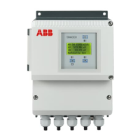
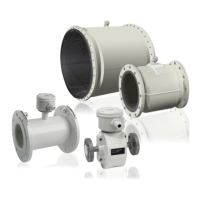
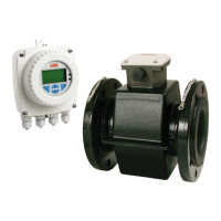
Description of the flowmeter system components and device designs.
Safety instructions and methods for transporting flange devices of different sizes.
General guidelines for installing the device in piping systems.
Requirements for grounding the flowmeter sensor for safety and measurement accuracy.
Step-by-step instructions for installing the flowmeter sensor.
Tightening torque values for flange and wafer type devices based on diameter and pressure.
General information and methods for grounding the device.
Steps for preparing and routing cables for SE21 and SE21F sensors.
How to connect signal and magnetic coil cables to the sensor terminal boxes.
Standard terminal assignments for the S4 transmitter and sensor connections.
Details on HART and PROFIBUS PA protocols for device communication.
Digital communication for PROFIBUS PA/FF and bus termination methods.
Essential checks before powering up and commissioning the device.
Parameters to check and set during on-site configuration for optimal operation.
A simplified procedure for quick and convenient transmitter setup.
Steps for commissioning PROFIBUS PA devices, including address setup.
Procedures for entering and modifying device parameters using controls or magnet.
How to measure coil AC current and voltage for fault detection.
How to measure coil DC resistance to detect shorts or other circuit issues.
How coil temperature is measured indirectly and factors affecting it.
How to measure coil insulation resistance to detect dampness or connection box issues.
Measuring electrode AC voltages to determine electrode balance.
Calculating electrode balance to detect distorted flow or installation issues.
Recommended minimum and maximum values for electrode voltage diagnosis.
Recommended diagnosis limit values for coil current based on fingerprint.
Recommended diagnosis limit values for coil voltage based on medium temperature.
Recommended diagnosis limit values for coil resistance based on medium temperature.
Structure and designation of error registers for various diagnostic parameters.
Procedure for readjusting coil temperature, including cable length and reference resistance.
Summary of error codes, their indicators, and related outputs.
Explanations of error codes, their causes, and corrective actions.
List of warning messages, their causes, and recommended corrective actions.
Safety precautions during maintenance and repair activities, including electrical and static discharge hazards.
Specifications for transmitter including measuring range, conductivity, power supply, and vibration.
| Category | Measuring Instruments |
|---|---|
| Manufacturer | ABB |
| Storage Temperature | -40 to 85 °C (-40 to 185 °F) |
| Humidity | 0 to 100% RH (non-condensing) |
| Protection Class | NEMA 4X |
| Mounting | Field mounting |
| Material | Stainless steel, aluminum |




 Loading...