FSM4000 ELECTROMAGNETIC FLOWMETER | OI/FSM4000-EN REV. E 15
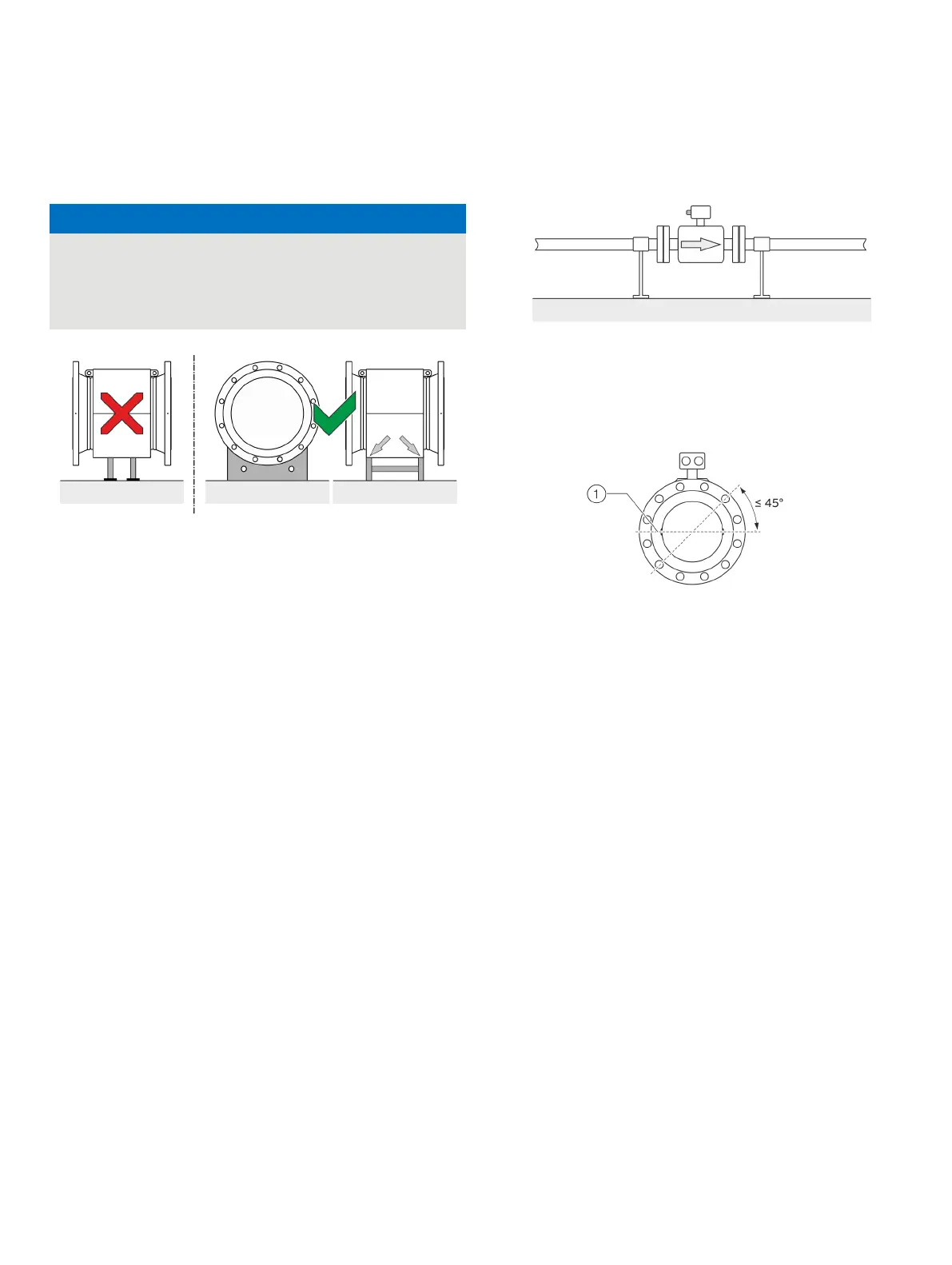
Brackets
Potential damage to the device!
Improper support for the device may result in a deformed
housing and damage to internal magnetic coils.
• Place the supports at the edge of the sensor housing (see
Figure 10: Support for nominal diameters greater than DN 400
Devices with nominal diameters larger than DN 400 must be
mounted on a sufficiently strong foundation with support.
Gaskets
The following points must be observed when installing gaskets:
• To achieve the best results, make sure that the gaskets
and meter tube fit concentrically.
• To make sure that the flow profile is not distorted, the
gaskets may not intrude in the piping cross-section.
• The use of graphite with the flange or process connection
gaskets is prohibited. This is because, in some instances,
an electrically conductive coating may form on the inside
of the meter tube.
Devices with hard rubber or soft rubber liner
• Devices with a hard / soft rubber liner always require
additional gaskets
• ABB recommends using gaskets made from rubber or
rubber-like sealing materials
• When selecting the gaskets, make sure that the tightening
torques specified in chapter Torque information on page 21
are not up-scaled.
Devices with a PTFE, PFA or ETFE liner
• In principle, devices with a PTFE, PFA or ETFE liner do not
require additional gaskets.
Flow direction
Figure 11: Flow direction
The device measures the flow rate in both flow directions.
Forward flow is the factory setting, as shown in Figure 11.
Electrode axis
Electrode axis
Figure 12: Orientation of the electrode axis
The flowmeter sensor should be mounted in the piping in such a
manner that the electrode axis is oriented as horizontally as
possible.
A maximum deviation of 45° from the horizontal position is
permissible.