FSM4000 ELECTROMAGNETIC FLOWMETER | OI/FSM4000-EN REV. E 35
Connecting the signal and magnet coil cables
signal cable
magnetic coil cable
Busbar (SE)
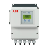
Figure 33: Transmitter
The outer shielding of the magnet coil cable is attached to the
busbar via the 6 mm clip (from the accessory bag in the
connection area). The outer shielding of the signal is routed in a
similar manner. Use the 7 mm clip (from the accessory bag in the
connection chamber). The shielding for the signal wires function
as a ‘driven shield’ to transmit the measurement signal. The
signal-reference voltage cable is attached to the sensor and
transmitter according to the electrical connection.
Note
The power supply of the FSM4000 with preamplifier is
connected via -U and +U, instead of 1S and 2S. If the flow
indicator shows the incorrect flow direction after successful
commissioning of the measuring system, e.g., reverse instead of
forward, correct this in the ‘Operating mode submenu’ of the
transmitter.
First switch off the programming protection (‘Prog. Level /
Specialist”). Then select the parameter ‘Directional display’ in the
‘Operating mode submenu’ and change ‘normal’ to ‘inverse’.
Finally, reactivate programming protection by selecting ‘Prog.
Level / Locked”).
Note
If the flowmeter sensor for older model meters (10D1422,
10DI1425, 10DS3111, DS4_, DS2_, 10D1462/72) is not yet equipped
with the SE clamp, the outer shielding is connected to one side
of the transmitter only. Use the 12 mm clip (from the accessory
bag), if necessary (e.g., 10D1422).
 Loading...
