Installation and commissioning guide
2750 515-1 EN, REV. 14, 2020-06-26
65
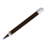
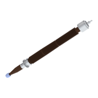
4. Connect the measuring equipment.
1. Connect the low voltage cable to the
stud (57).
2. Connect the high voltage cable to the
outer terminal.
3. Connect the ground cable to the bushing
flange (65).
G005048
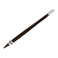
5.
Measure the capacitance (C
1
) between the outer terminal and the stud (57).
• Record the capacitance (C
1
) for future reference.
NOTE!
Refer to the table for the nominal capacitance (C
1
), Nominal capacitance, page 63.
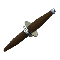
6.
Measure the capacitance (C
2
) between the stud (57) and the flange (65).
• Record the capacitance (C
2
) for future reference.
7.
Install the cover (58).
CAUTION!
The test tap is not self-grounding!
The bushing can be destroyed if the test tap is not grounded. Because the capacitance (C
2
)
is usually relatively small, the test tap must never be open-circuited when applying a
voltage to the bushing. It must always be grounded or connected to an external impedance.
CAUTION!
Do not energize the bushing without the cover or a test adapter installed. The cover
connects the outermost conductive foil to ground and will prevent damage to the bushing.
CAUTION!
Make sure that the cover is correctly installed with the O-ring in place, when the bushing is
not in use. The purpose is to prevent dust and water from entering the tap.
8.
Connect the outer terminal of the bushing to the external connections.
End of instruction