The document describes the Transformer bushing, type GOE 2600, an oil-impregnated paper bushing designed for immersed oil/air service. This installation and commissioning guide provides comprehensive information on its design, technical specifications, installation, maintenance, and disposal.
Function Description
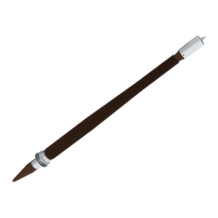
The GOE 2600 bushing facilitates the electrical connection between a transformer's internal windings and external power lines, while providing insulation and mechanical support. It is a capacitance-graded design, meaning it uses multiple conductive layers to control the electric field distribution, enhancing its insulation performance. The bushing is designed for outdoor use and is immersed in oil on the transformer side and exposed to air on the other.
A key feature is its test tap (70), connected to the outermost conductive layer of the condenser core. This tap is crucial for measuring the bushing's insulation properties (capacitance and dissipation factor) and must always be grounded or connected to an external capacitance when the bushing is energized to prevent damage. The cover (58) for the test tap grounds the condenser core.
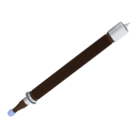
The bushing can be configured with one of two terminal systems:
- Draw-rod system: This system allows for the draw rod to be installed or removed, offering flexibility during transformer assembly and maintenance. It can include an optional additional joint (53) for transformers with short bushing turrets. All joints in the draw-rod system (39, 52, 56) must be locked with thread-locking fluid during operation.
- Fixed bottom contact system: In this configuration, the bottom contact (36) is pre-installed and fixed, simplifying installation in certain scenarios. It's crucial not to remove the six fixing bolts of the fixed bottom contact.
Important Technical Specifications
The GOE 2600 bushing is designed for transformers and is classified as an oil-impregnated paper, capacitance-graded, oil-immersed transformer bushing for outdoor use.
General Specifications:
- Ambient temperature limits: -40 °C to +40 °C.
- Maximum altitude of site: 1000 m.
- Level of rain and humidity: 1-2 mm rain/minute horizontally and vertically, according to IEC 60060-1.
- Maximum pollution level: According to the specific creepage distance and IEC 60815.
- Immersion medium: Transformer oil.
- Maximum daily mean oil temperature: +90 °C.
- Maximum temporary oil temperature (short time overload): +115 °C.
- Oil-level in transformer: Not lower than 30 mm from the bushing flange.
- Maximum pressure of medium: Pg 100 kPa (pg = relative to ambient pressure).
- Angle of installation: Vertical.
- Test tap: 8 mm male contact pin, conforming to IEEE type A.
- Maximum one minute test voltage: 20 kVrms.
- Operating voltage (when used as a power source with external capacitance): Limited to 6 kV.
- Conductor: Center-tube conductor.
- Markings: Conforming to IEC.
Mechanical Loading (Static Load on Outer Terminal):
- Test load 1 minute (N): 9500
- Maximum cantilever load in operation at installation angle 0° (N): 2500
- Maximum cantilever load in operation at installation angle >0° (N): On request.
- Maximum axial static load (N): 20000
- Maximum permitted torque on the outer terminal: 250 Nm.
Nominal Capacitance (for GOE 2600):
- C₁ ±10% (pF): 740 (capacitance between test tap and outer terminal).
- C₂ ±50% (pF)*: 6000 (capacitance between test tap and ground).
- Reference values from Hitachi ABB Power Grids. C₂ depends on the transformer and is not a fixed nominal value.
Usage Features
Installation:
- Lifting: The guide provides detailed instructions for safely lifting the transport box and the bushing itself, emphasizing the use of soft lifting slings and ensuring correct angles to prevent damage. Specific lifting tools (PDV1909-1, PDV1909-4) are required.
- Draw-rod system installation: Involves careful assembly of the upper and lower draw rods, ensuring correct threading and tensioning using a hydraulic jack (9769 897-A) and box spanner (9760 669-B). Thread-locking fluid (grade 42) and activator (grade 47) are essential for securing joints.
- Fixed bottom contact installation: A simpler process as the bottom contact is pre-installed.
- Winding cables: Must be installed without tension to prevent damage.
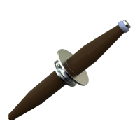
- Flange installation: Nuts should be tightened in a crosswise sequence, referring to transformer documentation for torque values. Plastic sleeves can be used to guide the flange and protect stud bolts.
- Outer terminal installation: Requires cleaning and lubrication of contact surfaces (47) and gasket surfaces (87) with Vaseline and Mobilgrease 28. The M8 bolts (24) are tightened with fingers, then the M10 bolts (6) are tightened in a crosswise sequence to 40 ±4 Nm, and finally the M8 bolts (24) to 20 ±2 Nm. A new O-ring (3) should be used for grid operation.
- Grounding: The bushing flange must be grounded to the transformer tank using a flexible cable (64) and a stainless steel A4-80 bolt (50) tightened to 40 Nm (M12).
Commissioning:
- Waiting time before energization: Crucial to allow air bubbles to dissipate. This varies based on storage position (vertical, inclined, horizontal) and transformer oil-filling method (vacuum, gas-saturated, de-gassed, reduced oil-level).
- Pre-energization tests: Recommended tests include tightness tests (between transformer and bushing flange, and of the bushing outer terminal), measurement of capacitance (C₁ and C₂), and dissipation factor (tan δ).
- Through-resistance measurement: Performed to detect large faults in the current path, comparing measured resistance to a reference value (difference less than 2% is acceptable).
Maintenance Features
The GOE 2600 bushings are generally maintenance-free, with no regular maintenance required.
Key maintenance aspects include:
- Cleaning of insulator surface: If exposed to high pollution, the insulator surface can be cleaned with a moist cloth or low-pressure water jet. Isopropyl alcohol can be used if necessary. Strong detergents like 1,1,1-Trichloroethane or Methyl-chloride are not recommended due to safety and environmental concerns. High-pressure water jets should be avoided to prevent damage.
- Thermovision (infrared camera) check: Recommended for local overheating on connectors. Significantly higher temperatures (above +35 °C to +45 °C above ambient) can indicate bad connections.
- Checking for oil leakage: Visual inspection during regular station supervision.
- Oil-level check: The oil-level must always be above the red area (29) on the oil-level indicator. If low, the bushing should be filled with clean and dry transformer oil when the bushing temperature is between +5 °C and +35 °C.
- Taking oil samples: Generally not recommended and should only be performed by authorized personnel.
- Post-repair capacitance measurement: Recommended after repairs or maintenance of connected equipment to detect any faults.
Safety Precautions:
- High voltage: Always disconnect and ground plant power before working on the bushing.
- Heavy objects: Ensure stability and do not walk under lifted objects.
- Transformer oil: Collect used oil in drums. Fumes can irritate respiratory organs and eyes; prolonged skin contact can cause damage. Treat liquid waste as hazardous.
- Fire: Extinguish fires with powder, foam, or carbon dioxide.
- Installation: Only authorized personnel should install the bushing, as incorrect installation can lead to catastrophic transformer failure.
- Hydraulic pressure: Apply carefully to avoid explosive force.
- Oil-plug: Open slowly to release pressure and prevent personal injury. Avoid power tools to prevent sparks and potential explosions.
- Stud bolts: Avoid damaging them during installation to prevent metal falling into the transformer.
- Draw rod: Be careful when pulling out the draw rod to avoid damaging the bushing's internal components.