Note/IllustrationAction
Art. no. is specified in Required
equipment on page 288.
xx0400001280
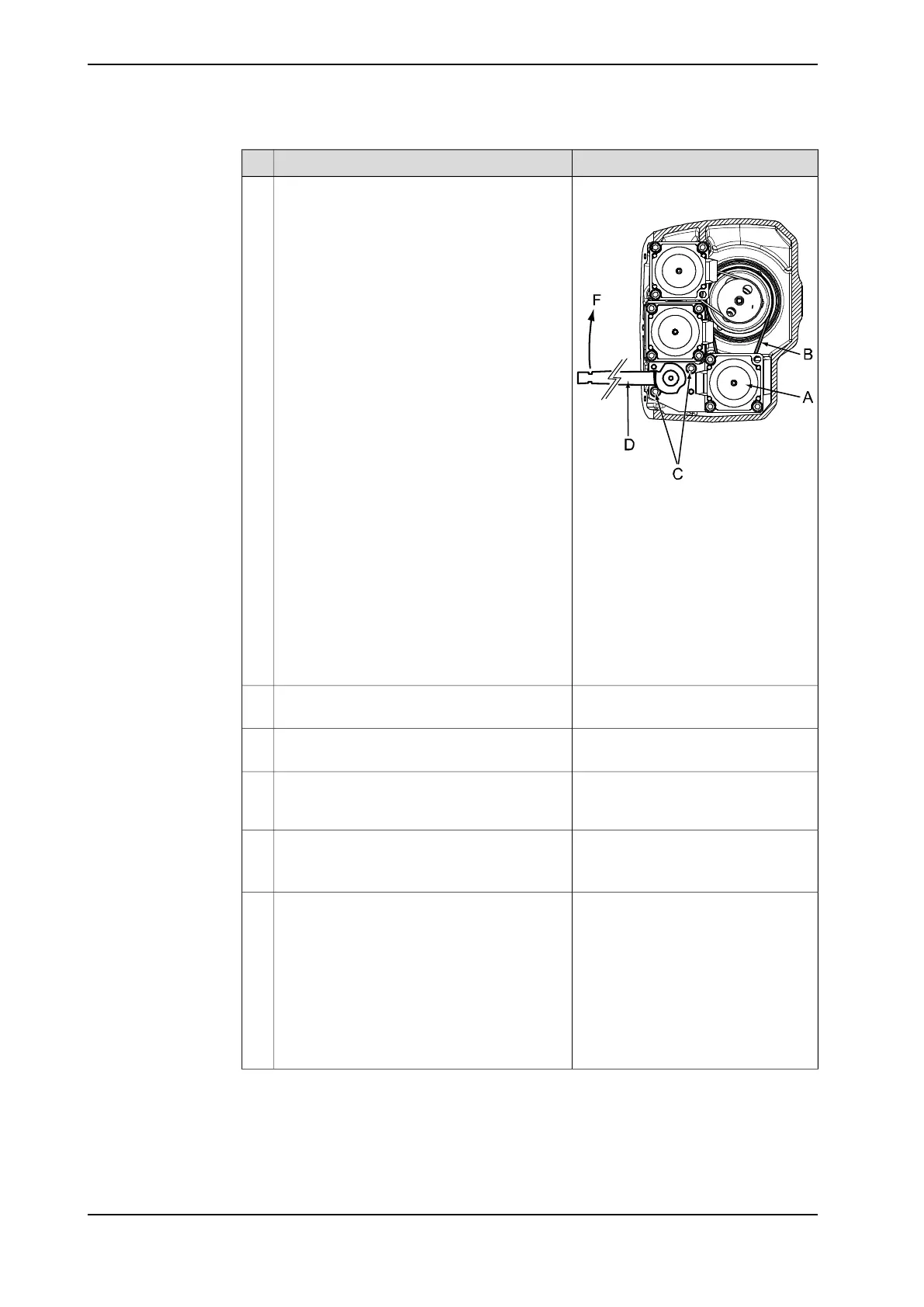
Follow the steps below when fitting the motor:
• Place the timing belt (B) round the motor
pinion and place the belt round the axis
5 as fitting the motor in the upper arm
housing.
• Fasten the motor bracket with two attach-
ment screws (C), but do not tighten the
screws yet. Use correct attachment
holes, shown in the figure to the right!
• Adjust the belt tension by pulling the
motor bracket, using the belt tightener
and dynamometer, as shown in the fig-
ure to the right.
• Tighten the two attachment screws of
the bracket (C) with a torque of 10 Nm.
4
A Motor axis 5
B Timing belt, axis 5
C Attachment screws and wash-
ers, motor bracket, 2 pcs, M6 x
20
D Belt tightener, the dimensions
are shown in the figure Belt
tightener, 3HAC 024044-001 on
page 289.
F (Force): 24 N.
Detailed in section Refitting, motor and
timing belt, axis 6 on page 313.
Refit the motor and timing belt of axis 6.5
Detailed in section Refitting, motor
axis 4 on page 282.
Refit the motor of axis 4.6
Cable layout shown in the figure Illus-
tration, cabling inside upper arm
housing on page 166.
Reconnect all connectors and place the cabling
correctly inside the upper arm housing.
7
Art.no. is specified in Required equip-
ment on page 288.
Refit the cover to the upper arm housing.
Check both the gaskets and replace, if dam-
aged.
8
Pendulum Calibration is described in
Operating manual - Calibration Pendu-
lum, enclosed with the calibration
tools.
Recalibrate the robot!9
Axis Calibration is described in Calib-
rating with Axis Calibration method on
page 349.
General calibration information is in-
cluded in section Calibration on
page 337.
Continues on next page
292 Product manual - IRB 1600/1660
3HAC026660-001 Revision: W
© Copyright 2006-2018 ABB. All rights reserved.
4 Repair
4.6.7 Replacement of motor and timing belt, axis 5, IRB 1600
Continued