Installing the LWT 23
—
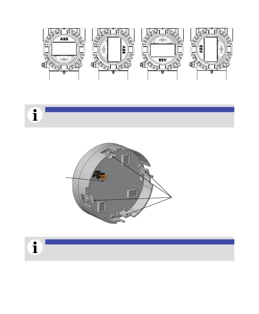
Figure 12 Four positions for the instrument HMI
+90° +180° +270°0° (default)
5 Properly align the connection pins and gently push back the HMI board on the communication
board, making sure that the four plastic locks are properly fixed.
NOTICE
Be careful not to bend the connection pins (see Figure 13) when pushing the board back in.
—
Figure 13 Connection pins on back of HMI board
Connection pins
Plastic locks
6 Hand tighten the housing cover back in place.
NOTICE
For Ex d and/or flameproof installations, see note “Securing housing cover in flameproof/
explosion proof areas” on page 30.

 Loading...


