1.7.4. Vertical distribution busbar
There are three standard vertical busbar types: full, three-
quarters and half distribution busbars. Both are located
inside the busbar compartment. These busbars
are arranged
in A-B-C order from left to right.
The combination of the numeric section code (1, 2, 3, etc.)
with the vertical level designation (A, B, C, and D) uniquely
describes each device’s location in the switchgear. For
example, the device mounted in the top of the first section
of a lineup would be coded 1-A.
Vertical bottom/full distribution busbar
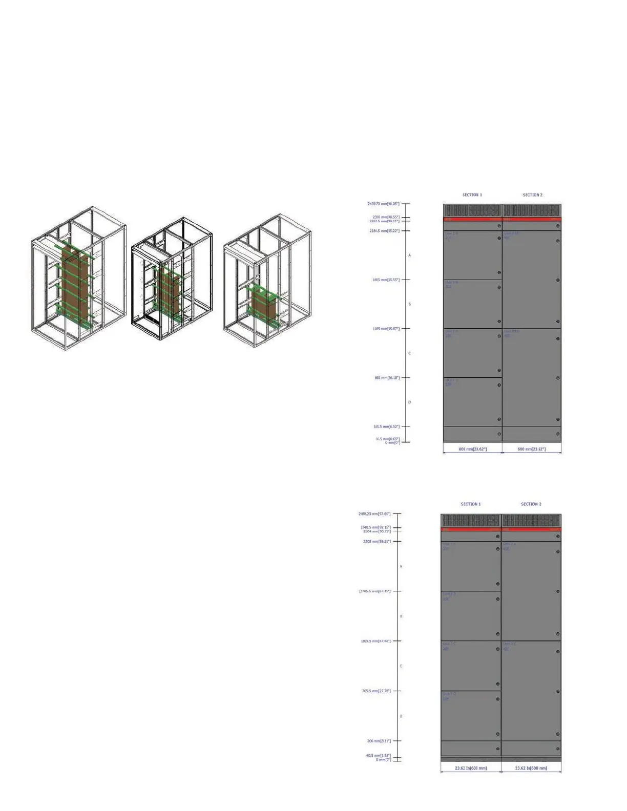
1.8. Device compartment
Each device compartment is divided vertically into four
locations, A through D. Locations A, B and D may contain
feeders, equipped space, control or blank. Location C may
contain main, tie, feeders or equipped space feeders.
Breaker unit instruments installed on the doors may include
only pilot lights, push buttons, control switches
and
maintenance switches.
In addition to the items listed above, instrument
compartments may also include ammeters, voltmeters, high-
resistance grounds (HRGs), potential transformers and
relays. These instruments can be installed inside the devices
or on the front of the device door.
1.8.1. Section and location numbering
Each section is sequentially numbered as the general
arrangement drawings are prepared. The left-most section
is usually section 1, the next section to the right
is 2, etc. This
numbering scheme ensures the correct sequencing of
vertical sections during installation.
Device location numbering
(C and D locations can be combined)