—
Locate and connect the switchgear
4. Locate and connect the switchgear
1. Before beginning the installation, ensure that you
have all
of the needed components:
-
Switchgear sections
-
Fastener hardware to connect sections
-
Shipping split connection hardware
2. Make a final check that all components are in good
condition. If there is any evidence of damage to the
equipment, contact an ABB representative to evaluate the
condition of the equipment before proceeding with
installation.
3. Carefully review all supplied project drawings and notes
to familiarize yourself with the layout and
construction of
the switchgear.
4. Based on the footprint shown on the general
arrangement drawings, mark the floor for all drill holes
necessary to fasten the switchgear or base frame to the
floor, and for cable conduits (if applicable). See
Fastening
Sections to a Base Frame.
5. Install power and secondary (control) conduits before
moving the switchgear to the site. The available space for
conduits appears on the floor plans supplied with the
switchgear. Conduits should not extend more than 1.0 in
(25mm) above floor level.
4.1. Installation location requirements
The installation must meet the following requirements:
-
Indoor location protected from moisture and dramatic
temperature changes. For longest equipment life, install
the switchgear in an enclosed room with temperature and
humidity control and filtered, and
forced air ventilation.
-
Level the site, preferably including a base frame that
is
either embedded in the concrete floor or rests on a false
floor on supports. The floor must be straight and
level to
+/- 1/4 inches (6 mm) over the entire length of the lineup.
-
Prepare proper openings in the floor, wall and ceiling
for
cables, conductors, pipes, bars and ventilation in
accordance with the construction drawings provided.
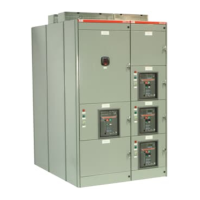
-
At least 2.5 ft (750 mm) from the top of the highest
section to the ceiling, and at least 3.0 ft (920 mm)
between the left and right end sections to the walls.
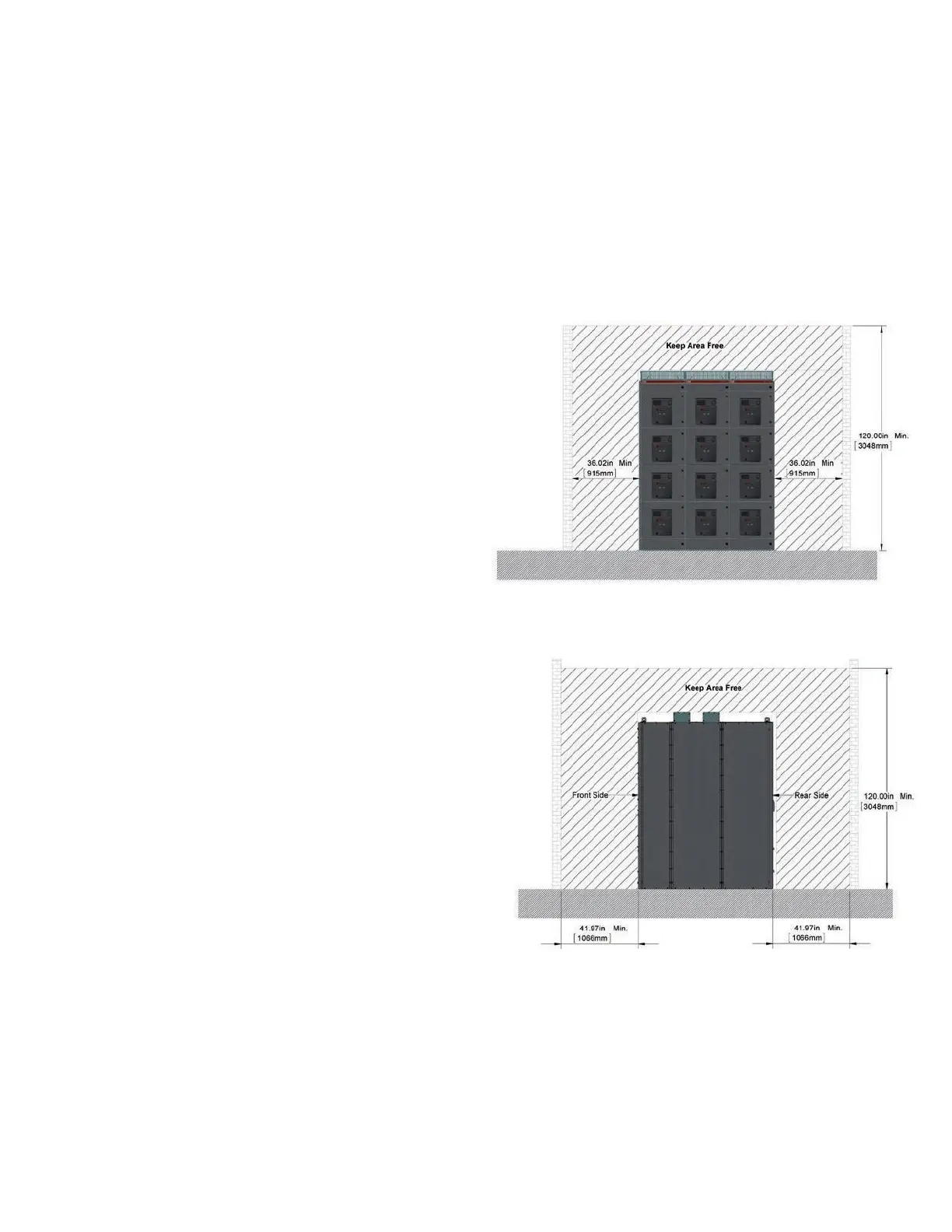
-
At least 3.5 ft (1066 mm) between the unit and
the rear
wall.
-
See Positioning Arc-Resistant Switchgear for special
restrictions regarding distances around the switchgear
and
other positioning requirements.
Clearances – front view
Clearances – side view
-
For sections with left-mounted doors, provide at least 3.0 ft
(920 mm) between the left wall and the left-end
section so
the doors can be opened more than 120°.
-
Ambient temperature is to be above -13° F (-25° C)
but not
exceeding 104°F (40°C) at 85% non-condensing humidity.
-
Supply sufficient space for future expansions,
if required.