-
Supporting brackets, beams, enclosures and foundation
frames should be painted or treated with corrosion-
resistant coating. To facilitate installation and
maintenance, the site should also have:
-
Convenient alignment with other equipment.
-
Accessibility for maintenance.
-
Adequate lighting.
-
Free access to the electrical equipment rooms.
4.2. Installation guidelines
Follow all instructions related to the installation of the
switchgear to avoid potentially hazardous situations that
could result in serious injury or death.
If the installation is being done near operational equipment,
it may be appropriate to erect temporary
barriers between
that equipment and the switchgear.
If you are adding sections to existing switchgear, turn off
all
power supplying this equipment before working on or
inside it.
Always use an appropriate voltage-sensing device to
confirm that the power is off prior to installing or working
with the switchgear.
Follow appropriate lockout/tagout procedures.
4.3. Section installation sequence
Sections can be installed or added in any order, and new
sections may be added between existing sections. If the
sequential order designated during manufacturing is
altered onsite by adding sections to an existing lineup,
the
main bussing must match; and the related drawings
must
be updated.
When adding, removing or rearranging sections, do not
exceed the maximum amperage available on the horizontal
bussing.
4.4. Install and connect shipping splits
NOTE: Diagrams showing the location of fasteners and the
appropriate torque values can be found in the
Torque Table
section of this manual.
4.4.1. Position shipping splits
Remove the shipping splits from their pallets or skids. If
you need to support a multiple- section shipping split at
the base after removing it from the pallet, use
supports at
the corner of each section. Don’t support
the shipping
split only at the four outer corners.
Position the shipping splits in their final arrangement
and
location. Connecting the sections together before
attaching
them to the floor and/or wall will simplify splicing the
horizontal bus.
If doors won’t close easily or panels are twisted or stressed,
this may indicate that the site is not leveled.
You may be able
to shim the sections to level them.
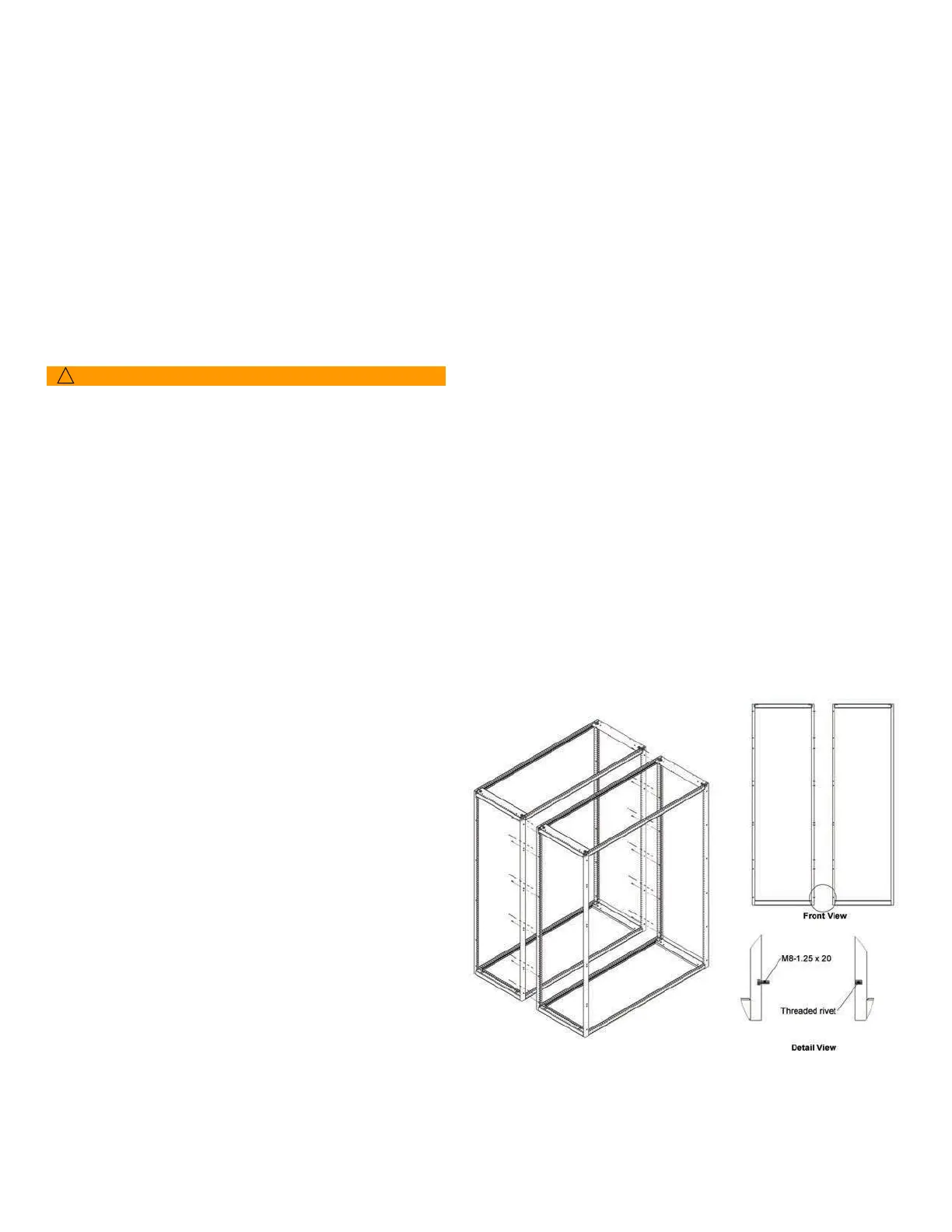
4.4.2. Connect sections
NOTE: Use only the provided fasteners to assemble
the
switchgear.
1. Begin the installation at either the left or the right
end of
the lineup by connecting the frames of the sections
together. The left side of each frame is fitted
with threaded
inserts. Sections are fitted on the right
side with the
necessary rivet nuts. Insert the bolts from the left side of
one frame to the inserts in the
adjoining section to the
right.
Frame connection using spacer bolts