9 | © 2022 ABB | - 1SDH002203A1002
ABB | E-kit
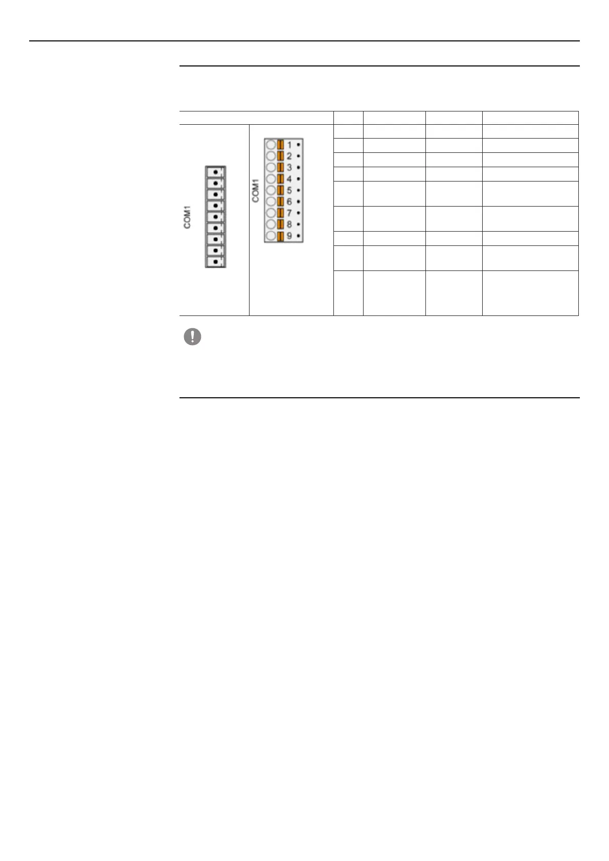
RS-485 serial communication interface (COM1 port)
4 - RS-485 serial communication interface (COM1 port)
Description of terminal box
E-kit is provided with a COM1 port with 9-pin removable terminal box for communication with the Modbus
RTU protocol.
Interface Pins Signal Interface Description
Terminal box
removed
Terminal box
plugged-in
1 Termination P RS-485 Termination P
2 Modbus + RS-485 Receive/Transmit, +
3 Modbus - RS-485 Receive/Transmit, +
4 Termination N RS-485 Termination N
5 RTS RS-232
Request to send
(output)
6 TxD RS-232
Transmit data
(output)
7 SGND Ground signal Ground signal
8 RxD RS-232
Receive data
(input)
9 CTS RS-232
Clear to send
(input)
WARNING!
Connector unused!
Make sure that the terminal box is always plugged into the terminals, even when there are no
cables connected.
Connection ports
A Modbus RS-485 network connects a Master device to one or more Slave devices.
Each device has a communication port with two terminals, conventionally called A and B. The communication
cable is connected in these two terminals so that all the devices taking part in the communication are
connected in parallel.
All “A” terminals must be connected to each other and all “B” terminals must be connected to each other,
respectively.
Note: Certain ABB devices, such as electrical metering instruments B21, B23, B24, are an exception. For
this reason, terminal M+ will now be indicated as the positive terminal while terminal M- will be indicated as
the negative terminal.
If connections “A” and “B” of a device are inverted, besides making them incapable of communicating, the
entire communication system may not function due to the incorrect direct current (bias) voltage values on the
terminals of the badly connected device.
To prevent errors when several devices are connected, it is advisable to use cables of the same color for
all connections to the A terminals and cables of the same color for all connections to the B terminals of the
different devices (e.g. white for A/M+ and red for B/M-). This makes it much easier to identify cabling errors.