GETTING TO KNOW YOUR PRODUCT 7
Preload
circuit
Preload
circuit
Preload
circuit
Preload
circuit
IGBT inverter
IGBT inverter
Output
filter
Output
filter
L
N
DC +
DC -
—
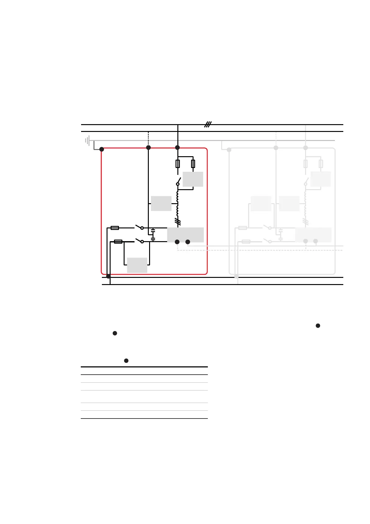
Figure 4: Schematic of PQstorI connections
2.3 Connection diagram
Figure 4 provides a schematic overview of exter-
nal connections to the PQstorI range of products.
Connection terminals are detailed in Table 1
above. Mandatory connections (depicted in solid
lines) are necessary for the product to operate.
Non-mandatory connections (dashed lines) en-
hance basic functionalities.
—
Table 2: LED signals in Figure 2
Item Input/ output connections
Red LED on and steady Module is off
Green LED on and steady Module is on or starting up
Red LED blinking Module has encountered
a critical error
Green and red steady Firmware is updating
Yellow LED blinking Wi-Fi traffic
2.4 LEDs
The green, red and yellow LEDs on the front of
the module ( in Figure 2) indicate the status
of the system:
2.5 Button operation
The button on the front of the Module ( in
Figure 2) starts and stops the system, acknowl-
edges faults and resets Wi-Fi user interface
settings:
Press the button once to start the Module,
stop the Module or acknowledge a system fault
(see Section 3.7.3)
Hold the button for 2 seconds to reboot
the Module (simulating a power outage)
Hold the button for 10 seconds to switch ON
or OFF Wi-Fi module
Hold the button for 15 seconds to reset
the Wi-Fi user interface settings
(see Section 3.8.3)
5
5
4
11
1 1
3
9
8
2
2
3
8
9