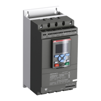
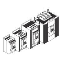
13OPERATING AND TROUBLESHOOTING INSTRUCTIONS
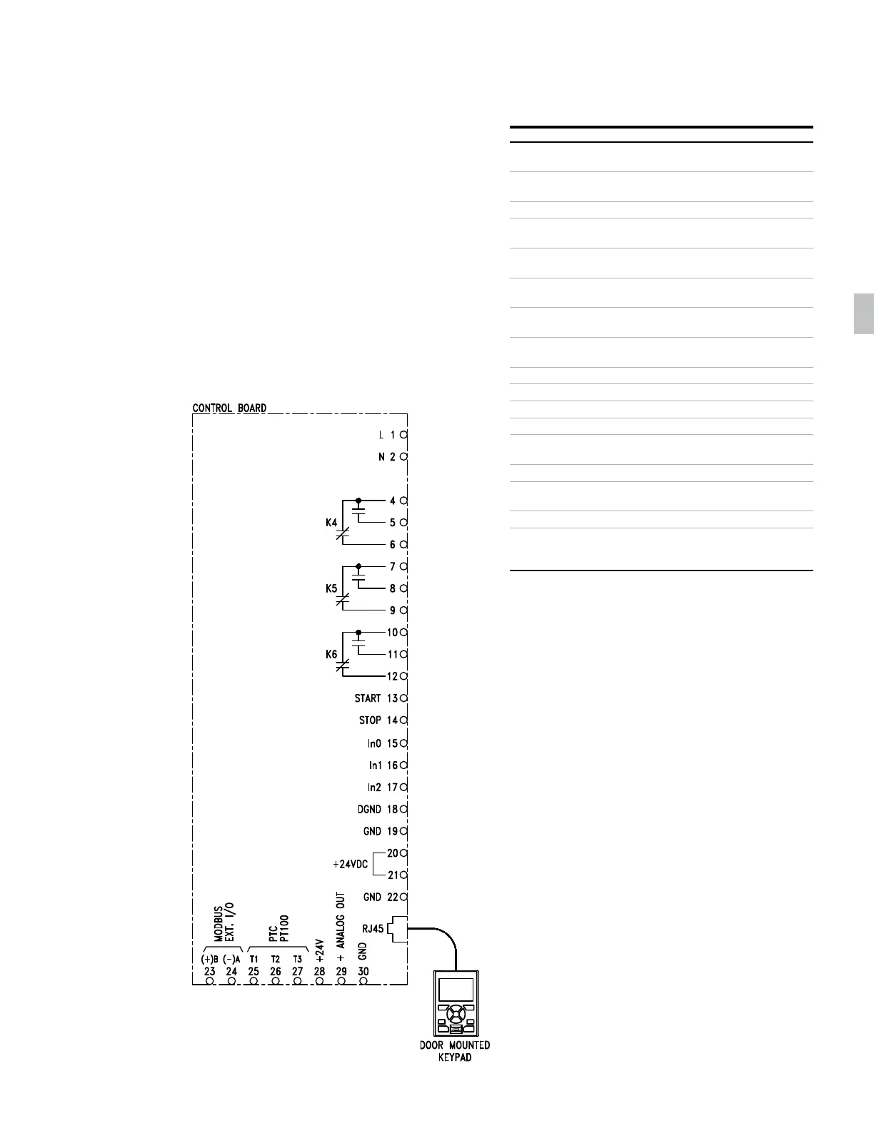
2. PSTX soft starter terminal board I/O
Any of the PSTX soft starter terminal board I/O
points, other than those already in use for proper
operation of the solid-state PSTX panel, are
available for customer use. The meanings and
connection diagrams for these I/O points are well
described and illustrated in the PSTX soft starter
user’s guide (1SFC132082M9901), which is supplied
with your panel documentation package. However,
several I/O points that will find frequent use in
BYPASS and NON-BYPASS panel applications
are described below for convenience. Refer to the
1SFC132082M9901 PSTX user’s guide for terminal
locations. Refer to the wiring diagram for details
on correct connection points.
Terminals Purpose
1L1, 3L2,
5L3
Connection to mains voltage up to 690 V
2T1, 4T2,
6T3
Connection to motor
GND Connection to ground
L (1) Control power phase
(120 V AC from supplied CPT)
N (2) Control neutral (return)
(120 V AC from supplied CPT)
4, 5, 6 Programmable output relay terminals
(K4 is used for the RUN pilot light)
7, 8, 9 Programmable output relay terminals
(K5 is not used)
10, 11, 12 Programmable output relay terminals
(K6 is used for the FAULT pilot light)
13, 14 Start and stop terminals
15, 16, 17 Programmable input terminals
18, 19, Start and stop terminals
20, 21 Start and stop terminals
22 Connect the functional ground to a
ground point close to the soft starter
23, 24 Modbus ext. I/O
T1, T2, T3
(25, 26, 27)
Thermistor input is programmable
as a PTC type thermistor, PT100
28, 29, 30 +24 V, +analog out and GND
AJ45 RS 485 communication (built into PSTX unit);
the RJ45 connection is a cable connection to the
HMI keypad mounted to the front of the enclosure
Note: 120 V A C connected to any digital terminals
from 13 through 17 will damage the control board.
3. Adjustments
The solid-state PSTX panel offers several user-
settable adjustments, which allow it to be tailored
specifically for your three-phase induction motor.
Setting these adjustments appropriately is an
important factor in ensuring that applicable safety
codes are met and that your panel, wiring and
motor are adequately protected. The following
list comprises all of the user-adjustable devices/
components inside the solid-state PSTX panel. The
user may wish to have a copy of NFPA 70 (commonly
known as the National Electrical Code, or simply
NEC) available for reference when setting these
adjustments.
Input fuses
In general, there are two configurations that use
input fuses: 1) input disconnect with load side
separately mounted fuses; and 2) input fused
disconnect where fuses are an integral part of
the disconnect. If your panel was ordered with the
circuit breaker option, the disconnect device and
fuses are replaced by the circuit breaker. For fused
disconnect panels, the main input fuses provided
with your panel have been closely coordinated to
03