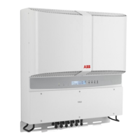
During installation do not place the
inverter with the front cover facing
towards the ground.
• Position the bracket
01
so that it is
perfectly level on the wall and use it
as a boring template.
• Make the 3 holes required, using a
drill with a 10 mm diameter bit. The
depth of the holes should be about
70 mm. On the bracket
01
there are
5 holes with which to secure it: just 3
are enough to support the inverter if
installed on stable, robust supports.
• Secure the bracket to the wall
A
or
to the pole
B
with the no. 3 x 10 mm
wall plugs supplied with it (Step 1).
Check the stability of the bracket and
if necessary use all the xing points
(5) there are on the bracket.
• Hook the inverter to the bracket
spring corresponding with the inser-
tion point in the bracket on the back
of the inverter (Step 2).
• Proceed to anchor the inverter to
the bracket
01
by tightening the lo-
cking screw
02
located on the lower
side (Step 3).
• Unscrew the 4 screws and open the
front cover
05
in order to make all the
necessary connections.
• Once the connections have been
made, close the cover by tightening
the 4 screws on the front to a mini-
mum tightening torque of 1.5 Nm.
Wall/Pole mounting
A
B
UNO
POWER
ALARM
GFI
ESC
UP
DOWN
ENTER
1

 Loading...
