12
EN
(Continue to next page)
• Use the two M8 screws with flat and spring washers (sup-
plied) to fix the pieces of the bracket together.
• Position the bracket (03) perfectly level on the support and
use it as drilling template.
Consider the overall dimensions of the power module and
the wiring box.
• It is the installer’s responsibility to choose an appropriate
number and distribution of attachment points. The choice
must be based on the type of support (wall, frame or other
support), the type of anchors to be used, and their ability to
support 4 times the inverter’s weight (4x125Kg=500Kg for all
models).
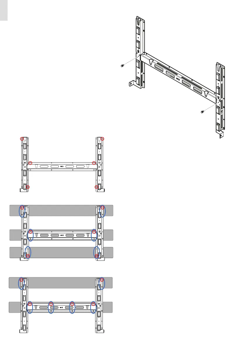
• Attach the bracket (03) to the support with at least 6 attach-
ment screws (shown in RED) or at least 6 frame fixing bracket
for frame mounting (shown in BLUE).
• Depending on the type of anchor chosen, drill the required
holes to mount the bracket (03). The pictures shown the rec-
ommended minimum fixing point depending to the type of
support.
Wall/Floor mounting
minimum fixing points
Frame mounting (3 supports)
minimum fixing points
Frame mounting (2 supports)
minimum fixing points
 Loading...


