84 Product manual - PVS-175-TL;A.1 Version
EN
5.9.4 Serial communication connection (RS485 - Slave mode)
NOTE – D Please note that automatic settings of network parameters at turning on, embedded
logging capability, automatic logger-free transferring of data to Aurora Vision Cloud and
remote firmware update are provided over TCP/IP (Ethernet and/or Wi-fi) bus only.
NOTE – D The use of the inverters over the RS485 line is recommended in case of monitoring and
controlling by using third party RS485 control systems.
NOTE – D By default the RS485 port (43) is set as Slave mode. In case the port was set as “Master
mode” it must configured through the Web User Interface (refer to “CONNECTIVITY menu”
section) to use the RS485 as a serial communication line.
NOTE – D RS485 line supports Modbus/RTU SUNSPEC compliant Modbus protocol.
The RS-485 port can be used to set up a line of communication which, when connected to a monitoring
device, enables the operation of the photovoltaic system to be kept under control. Depending on the
device used, monitoring can be local or remote.
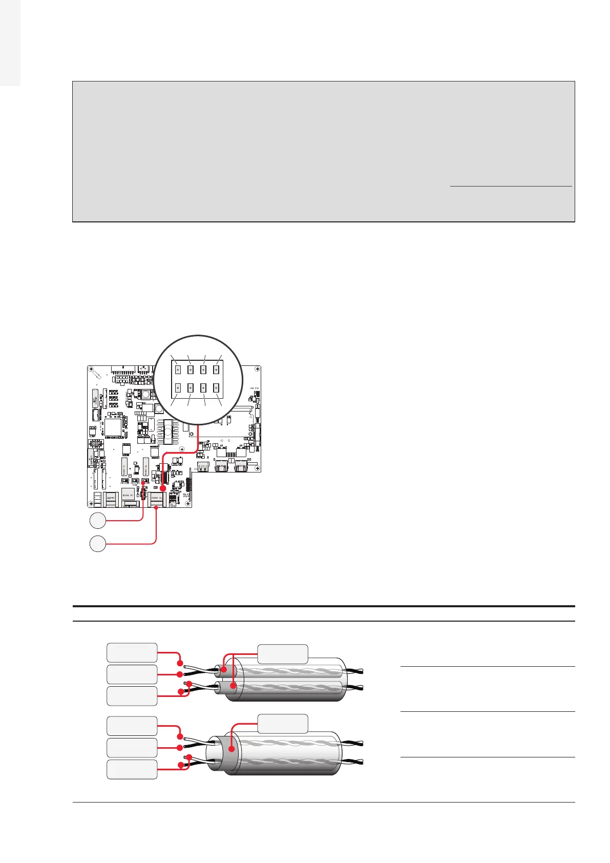
The RS-485 serial communication line is available on the communication and control board (26) with two
terminal blocks (43) for each serial line signal (+T/R, -T/R and RTN) so as to be able to make a daisy-chain
connection (“in-out”) of multiple inverters.
J10J9
X1
J6
J1
J4
S2 S1 S3
J7 J8
J20
X2
J2
J3
1
18
2 3 4
1 4
18
7
82
1
485+ RTN485-
485+ RTN
SHIELD
SHIELD485-
40
43
For long distance connections is necessary to use a shielded twisted pair cable with characteristic
impedance of Z0=120 Ohm as shown on the following table:
Signal Symbol
SHIELD
+ 485
+ 485
- 485
- 485
RTN
RTN
SHIELD
Positive data + 485
Negative data - 485
Reference RTN
Shield SHIELD