60 Product manual - PVS-175-TL;A.1 Version
EN
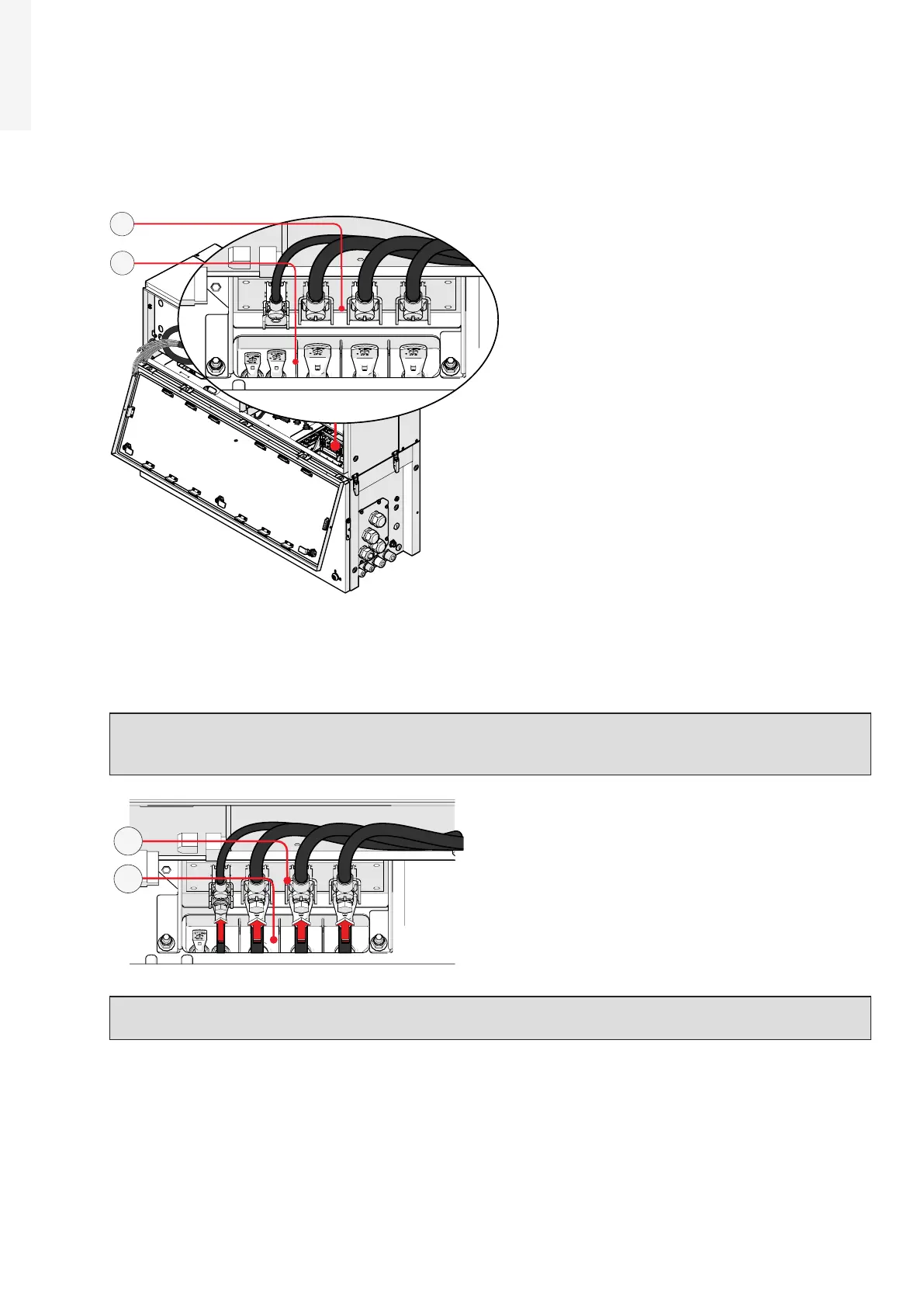
5.4.6 Connection of the AC interface power cables
The AC interface power cable (31) (RST phases, PE and MID BULK) are situated into the cable housing on
the top side of wiring box (02).
31
34
•
Install the R, S and T phases and MID BULK cable lugs (31) (coming from the wiring box) to the respective
AC interface connection point (34) inside the power module, paying attention to the correspondence of
the phases with the labels, using the M6 bolts (for phases) and the M5 bolt (for MID BULK) supplied in
the power module installation kit.
ATTENTION – A The cable lugs must be installed with a tightening torque of:
M6 bolt (R,S,T phases) = 5Nm
M5 bolt (MID BULK) = 3Nm
34
31
ATTENTION – A In case of a wrong phase sequence the inverter will not connect to the grid and
it will provide an error state.