Electrical installation 89
Connecting the external power supply cable for the
auxiliary circuit
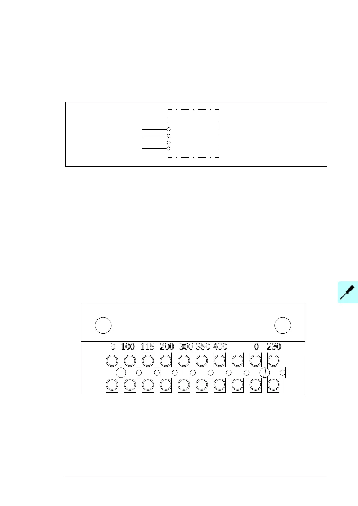
Connect the external power supply cable conductors to the terminals of auxiliary control
voltage switch Q10 as shown below. For the location of the switch inside the cabinet, see
the cabinet layout photos in chapter Operation principle and hardware description.
Maximum fuse: 16 A
Note concerning power supply from IT (ungrounded) systems: Contact ABB for
instructions. Equip the power supply for the auxiliary circuit with fault current circuit
breakers for ground fault indication and tripping. If the overvoltage protection device of the
auxiliary control voltage input causes unnecessary ground fault trippings, the type of the
device must be changed.
Checking the wiring of the auxiliary voltage transformer
(options +G396, +G397, +G398 and +G415)
The connections of the auxiliary voltage transformer (T10) are made at the factory. Check
that the connections agree with the selected option code (+G396, +G397, +G398) or the
used main voltage (+G415). If not, change the connection wire to the correct voltage
terminal.
 Loading...


