Operation principle and hardware description 25
No. Description No. Description
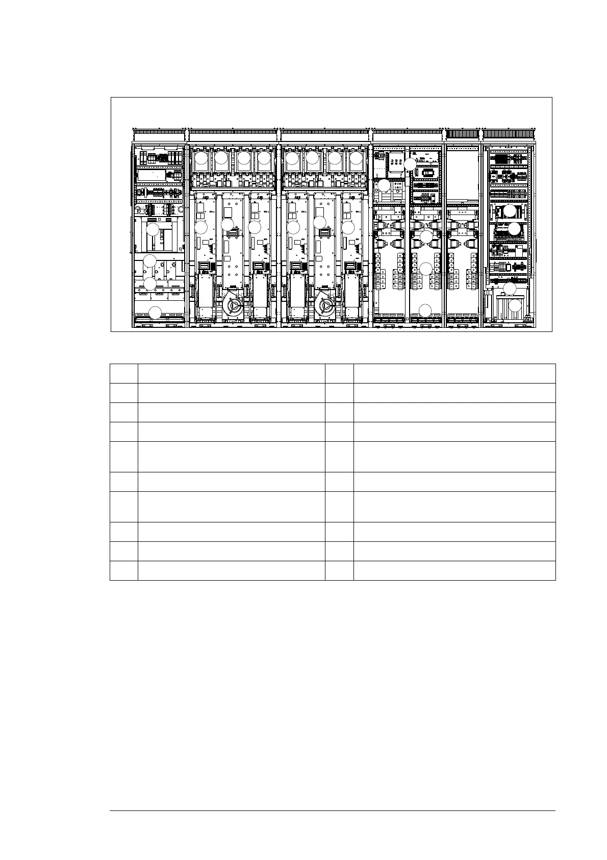
1. DC cable lead-throughs 10. AC contactor
2. DC input cable terminals (fuse protected) 11. Inverter power module
3. Input DC fuses 12. LCL filter
4. Temporary grounding points for the DC
busbars
13. AC output cable lead-throughs
5. DC main switch 14. AC output cable terminals
6. Aux. transformer 15. Temporary grounding points for the AC
busbars
7. Main control board 16. AC breaker
8. PLC 17. User I/O connection terminals
9. DC contactor
Front view
10
9
9
10
10 9
10
9
5
4
8
12
12
11
11 11
11
16
7
3
15
2
14
6
13
1
17