54 Technical data
Power factor (cos phi
1
)
adjustment range
0…1 capacitive or inductive depending on the dimensioning
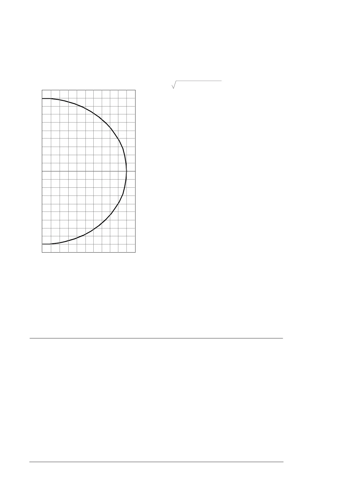
The following graphs illustrate the equipment operation with the nominal AC
voltage and nominal ambient temperature. Refer to Ratings on page 46.
Current Refer to Ratings on page 46.
Max. output fault current
(AC short-circuit test)
Peak: 7.0 kA
Duration: 3 ms
3 cycles: 1.5 kA
Overvoltage category
(IEC 62109, IEC 60664-1)
OVC III
Harmonic distortion THD current < 3% at nominal load
DC input connection data
Maximum DC power (P
pv
) Refer to Ratings on page 46.
Maximum DC current
(I
max(DC)
)
Refer to Ratings on page 46.
Maximum DC voltage
(U
max(DC)
)
1000 V DC
Operational DC voltage
range, U
mppt(DC)
PVS800-57B-1645kW-C: 550...1000 V DC
PVS800-57B-1732kW-C: 580...1000 V DC
Voltage ripple < 3%
Overvoltage category
(IEC 62109, IEC 60664-1)
OVC II
Short-circuit withstand
strength
6kA
Allowed electrical system
types
Floating as standard, plus or minus pole grounded with options (+F282 and
+F283)
Maximum backfeed current 24 inputs: peak 18 kA, 3 cycles 1900 kA, duration 600 µs
P/P
N
(%)
Q (%)
90
80
70
60
50
40
30
20
10
0
-10
-20
-30
-40
-50
-60
-70
-80
10 20 30 40 50 60 70 80 90 1000
100
-90
-100
Q Reactive power in percentage of nominal
active power
P/P
N
Relative active power
10 000 - P
act
2
Q
max = 0.9 *