24 Operation principle and hardware description
Layout overview
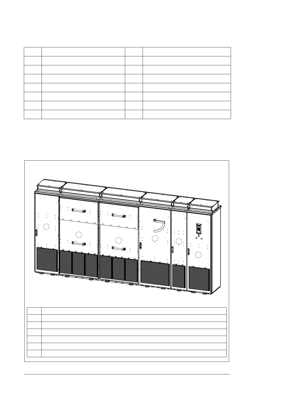
An example of the inverter construction is shown below. An optional DC cabinet is
displayed in these figures. Cabinet order and door opening direction can also be different.
Code Description Code Description
F2 AC fuses K2 AC contactors
F3 DC input fuses U1 Power modules
F40 Backup fuse for SPD U2 LCL filters
F41 DC side SPD Q1 DC disconnector
F50 Backup fuse for SPD Q2 AC breaker
F51 AC side SPD A21 Grounding option
K1 DC contactors
Item Description
AAC cabinet
B ISU cabinet 1
C ISU cabinet 2
D DC cabinet 1
E Optional DC cabinet 2
FAUX cabinet
Front view
A
B
C
D
E
F