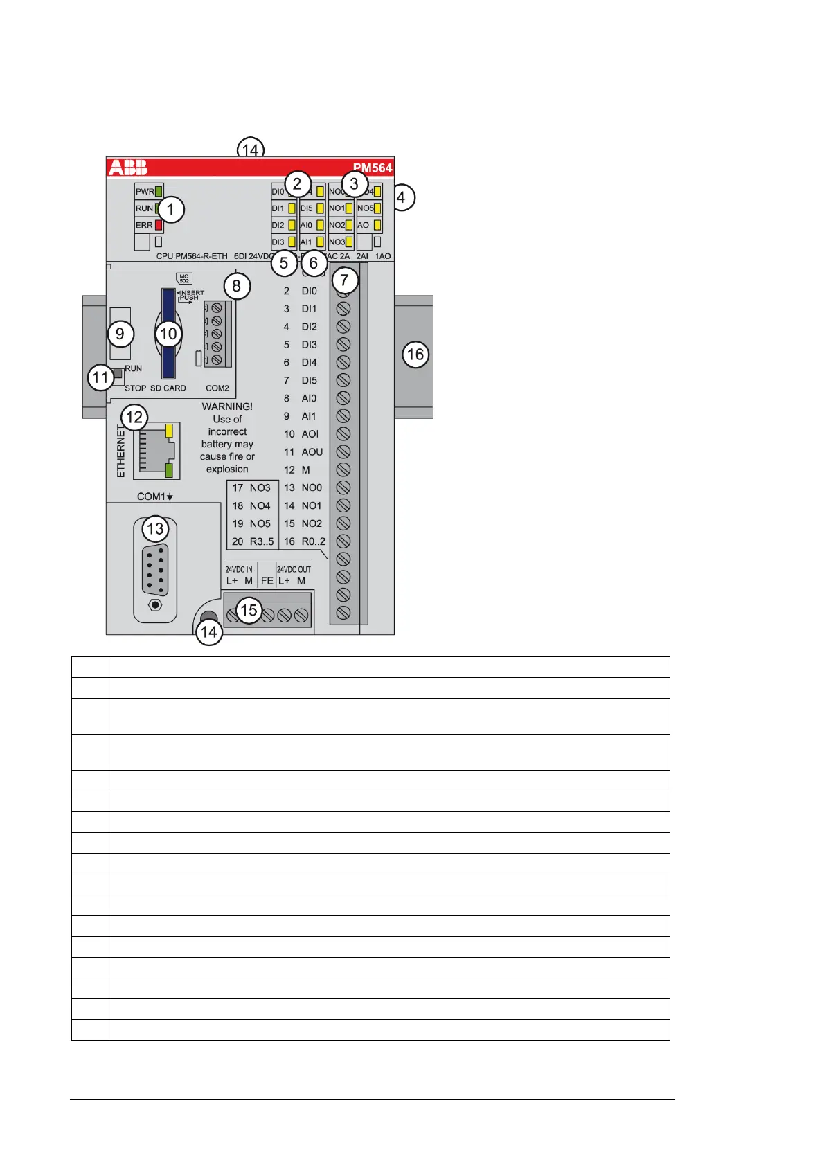
No. Description
1. 3 LEDs show the status of the CPU
2. 6 yellow LEDs show the status of the digital input signals
2 yellow LEDs show the status of the analog input signals
3. 6 yellow LEDs show the status of the digital output signals
1 yellow LED shows the status of the analog output signal
4. I/O bus for additional I/O modules
5. Terminal number
6. Allocation between terminal number and signal name
7. Terminals for the input and output signals (20-pin, not removable)
8. 5-pin removable connector for COM2 (optional)
9. Handle for opening the cover for the expansion modules
10. SD memory card slot (optional)
11. RUN/STOP switch
12. Ethernet interface
13. 9-pin SUB-D jack (COM1) for RS-485 connection
14. 2 holes for wall mounting with screws
15. 5-pin removable connector for power supply (24 V DC or 100-240 V AC depending on model)
16. DIN rail