Section 3 1MRK 500 124-UEN
HMI500
38 Operation Manual
Distributed busbar protection REB500
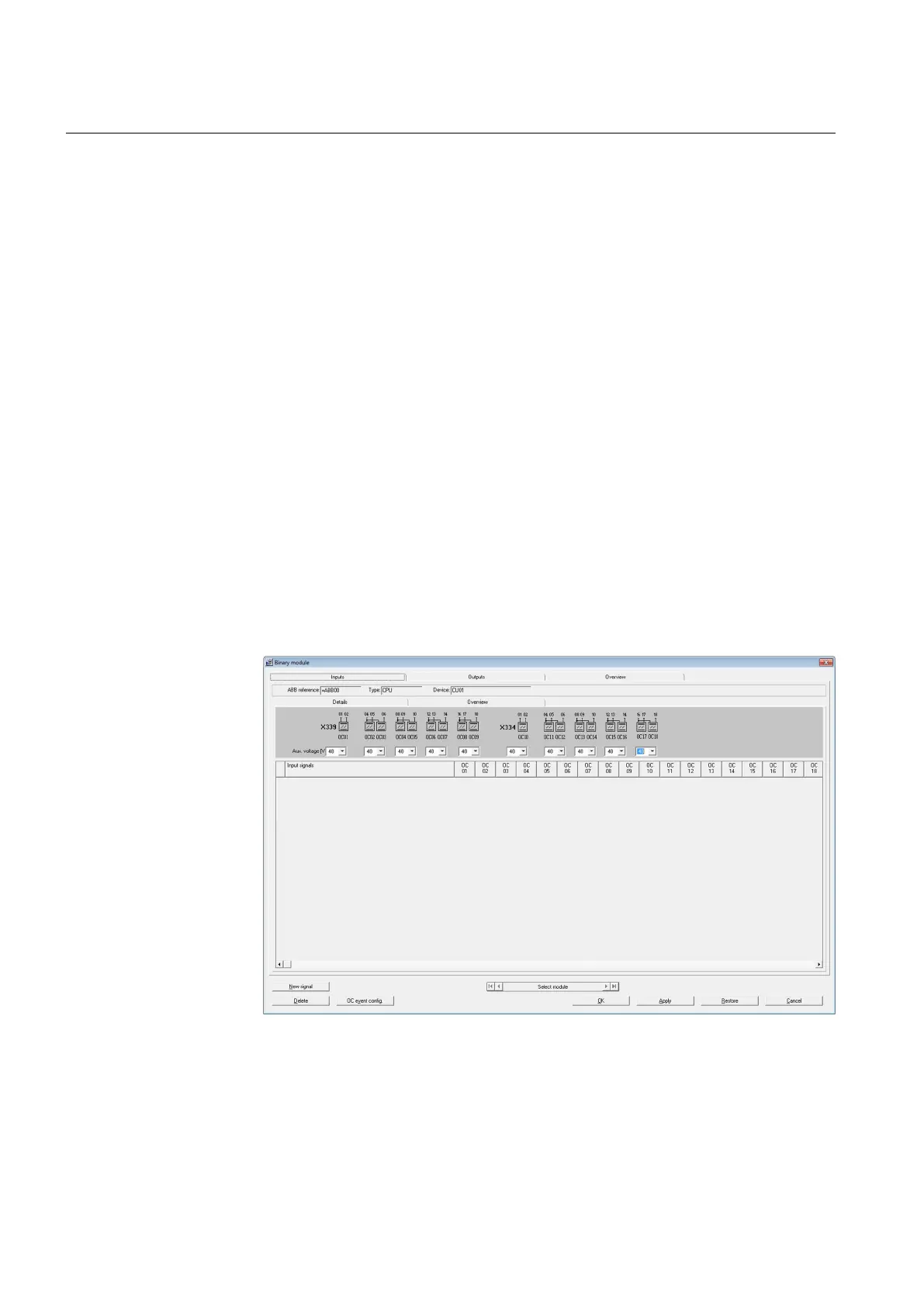
3.6.3.3 Inputs Overview tab
The upper part of this tab contains the general input layout. The auxiliary supply
voltage for each group of optocouplers (with a common pole) is placed below this.
The combo box is used to select a new value for the auxiliary supply voltage
(battery voltage).
In the matrix below, all the input signals assigned to the device are listed.
Delete a Signal:
Select a row in the list and click the button “Delete”.
Optocoupler event configuration:
Select a column (e.g. OC08) and click the button “OC event config.”.
In addition to events generated by function signals, a physical input can also be
configured as an event. This is of advantage, for example, when several signals are
assigned to a physical input or when ambivalent signals from isolators or circuit-
breakers need to be recorded.
To configure a physical input as an event select it in the list and click on “OC event
config.” to open the “Configuration of events” window.
Figure 26 Configuration / Binary module - Central unit inputs