Section 4 1MRK 500 124-UEN
Local HMI
74 Operation Manual
Distributed busbar protection REB500
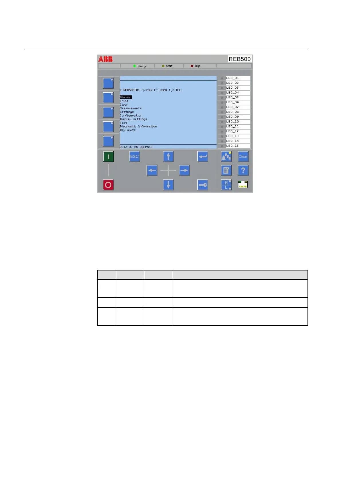
Fig. 4.1 Local human-machine-interface (LHMI)
4.3.3 Protection Indicator LEDs
There are three LEDs on top of the display: green, yellow, and red.
Table 17 Local HMI Protection Indicator LEDs
LED IEC label ANSI label Description
green Ready Normal Flashes while the system is being initialized. Continuously lit
during normal operation.
yellow Start Pickup Not used.
red Trip Trip Indicates a trip. Remains lit until applying a binary signal to the
reset input or selecting the HMI function “Reset latching“.
4.3.4 LED signals
The local HMI contains 15 additional LEDs, each of which can be assigned to any
output signal and configured to latch or not to latch as required.
Refer to section 3.6.6 “HMI LEDs”