Section 3 1MRK 500 124-UEN
HMI500
18 Operation Manual
Distributed busbar protection REB500
3.5 View menu
3.5.1 Single-line diagram
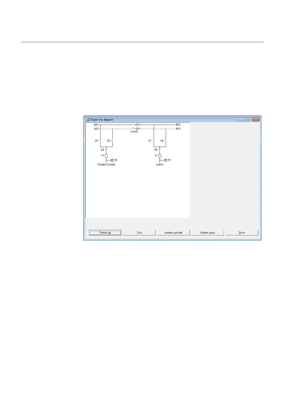
This menu item displays a diagram of the plant corresponding to the layout of the
connection diagrams created by ABB. The screenshot in Figure 8 shows an
example of a single-line diagram.
Figure 8 Typical single-line diagram
The name of every item of a plant can be changed by pointing at its symbol and
clicking the right mouse button. This opens the “Change label” context menu to
open the corresponding dialog. After entering the new name, click on “OK” to
confirm.
Click the button “Update Status” or “Update Cyclically” to show the actual bay
measurements and the state symbols of the configured breakers and isolators.
It is also possible to display the differential currents of the selected busbar zone.
Point on the end of a busbar zone (e.g. BZ1) and click the right mouse button to get
the corresponding context menu.
Click the right mouse button in an empty field in the single-line diagram to view a
dialog with a list of the symbols used (see Figure 9). The buttons on the right