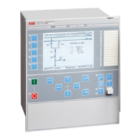
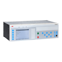
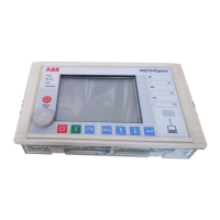
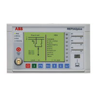
Table 201. Maximum quantity of I/O modules, with compression terminals
When ordering I/O modules, observe the maximum quantities according to the tables below.
Note: Standard order of location for I/O modules is BIM-BOM-SOM-IOM-MIM from left to right as seen from the rear side of the IED, but
can also be freely placed.
Note: The maximum quantity of I/O modules depends on the type of connection terminals.
Case sizes
BIM IOM BOM/
SOM
MIM Maximum in case
1/1 x 19” rack casing,
one (1) TRM
14 6 4 4 14 *)
1/1 x 19” rack casing,
two (2) TRM
11 6 4 4 11 *)
3/4 x 19” rack casing,
one (1) TRM
8 6 4 4 8 *)
3/4 x 19” rack casing,
two (2) TRM
5 5 4 4 5 *)
1/2 x 19” rack casing,
one (1) TRM
3 3 3 1 3
*) including a combination of maximum four modules of type BOM, SOM and MIM
Table 202. Maximum quantity of I/O modules, with ringlug terminals
Note: Only every second slot can be used.
Case sizes BIM IOM BOM/
SOM
MIM Maximum in case
1/1 x 19” rack casing,
one (1) TRM
7 6 4 4 7 **) possible locations: P3, P5, P7, P9, P11, P13, P15
1/1 x 19” rack casing,
two (2) TRM
5 5 4 4 5 **) possible locations: P3, P5, P7, P9, P11
3/4 x 19” rack casing,
one (1) TRM
4 4 4 4 4 **) possible locations: P3, P5, P7, P9
3/4 x 19” rack casing,
two (2) TRM
2 2 2 2 2, possible locations: P3, P5
1/2 x 19” rack casing,
one (1) TRM
1 1 1 1 1, possible location: P3
**) including a combination of maximum four modules of type BOM, SOM and MIM
1MRK 511 404-BEN A
Product version: 2.2.1
ABB 123
 Loading...
