The analog channels have fixed connections towards the different function blocks
inside the protection relay’s configuration. Exceptions from this rule are the eight
analog channels available for the disturbance recorder function. These channels are
freely selectable and a part of the disturbance recorder’s parameter settings.
The analog channels are assigned to different functions. The common signal marked
with 3I represents the three phase currents. The signal marked with Io represents the
measured residual current via a core balance current transformer. The signal marked
with Uo represents the measured residual voltage via open-delta connected voltage
transformers.
The EFHPTOC protection function block for double (cross-country) earth-faults uses
the calculated residual current originating from the measured phase currents.
3.4.3.1 Functional diagrams for protection
The functional diagrams describe the protection functionality of the protection relay
in detail and picture the factory default connections.
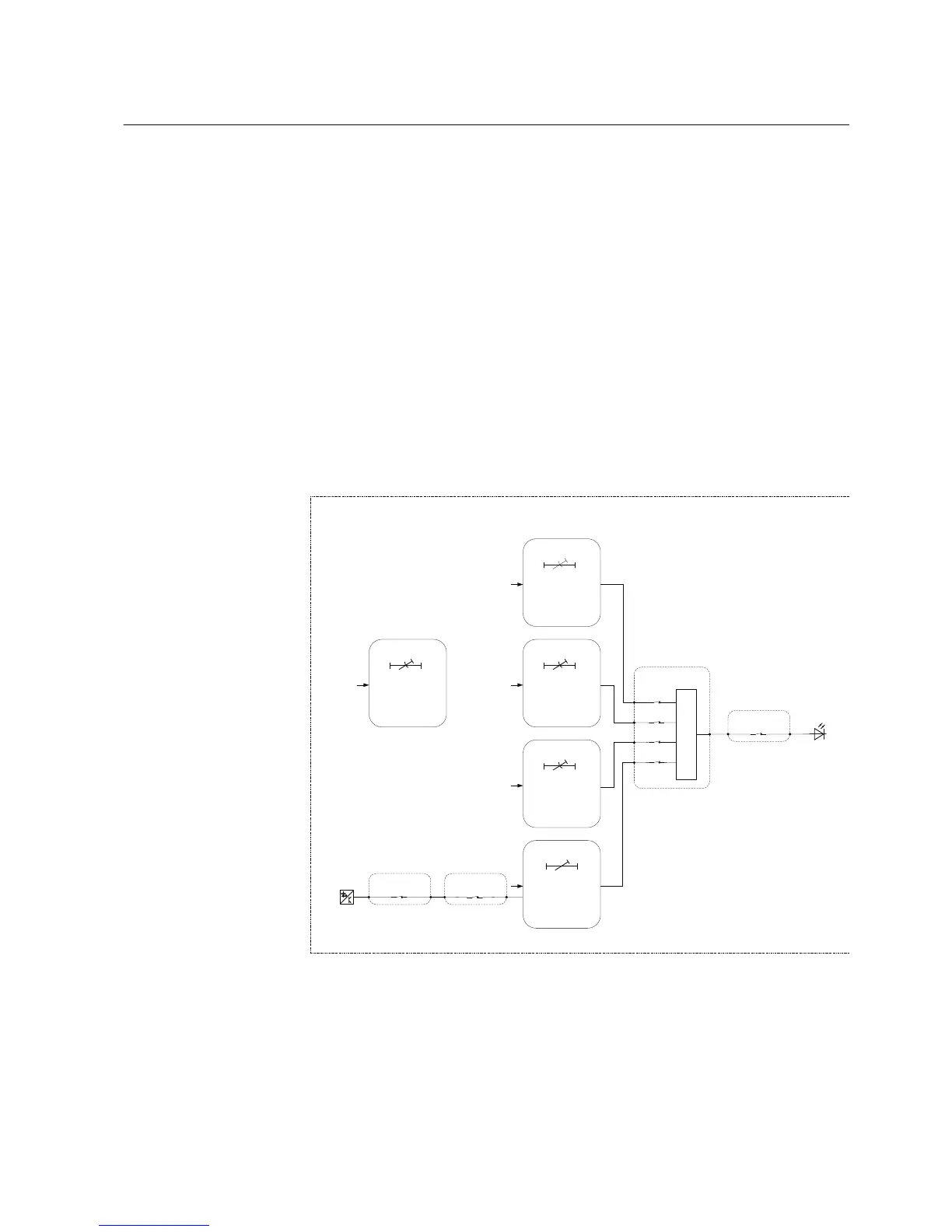
GUID-7490603E-FE2C-4241-A98B-2CE7C935C0FB V1 EN
Figure 16: Overcurrent protection
Four overcurrent stages are offered for overcurrent and short-circuit protection. The
instantaneous stage PHIPTOC1 can be blocked by energizing the binary input
(X120:1-2). The inrush detection block’s INRPHAR1 output BLK2H enables either
1MRS757456 D Section 3
REF611 standardized configurations
REF611 37
Application Manual