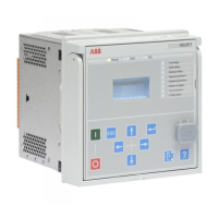
Section 4 Protection relay's physical connections
4.1 Inputs
4.1.1 Energizing inputs
4.1.1.1 Phase voltage
Table 16: Phase voltage inputs
Terminal Description
X130:11-12 U1
X130:13-14 U2
X130:15-16 U3
Table 17: Reference voltage measurement
Terminal
Description
X130:9-10 U12B
4.1.1.2 Residual voltage
Table 18: Residual voltage
Terminal
Description
X130:17-18 Uo
4.1.2 Auxiliary supply voltage input
The auxiliary voltage of the protection relay is connected to terminals X100:1-2. At
DC supply, the positive lead is connected to terminal X100:1. The permitted auxiliary
voltage range (AC/DC or DC) is marked on the top of the LHMI of the protection
relay.
Table 19: Auxiliary voltage supply
Terminal
Description
X100:1 + Input
X100:2 - Input
1MRS758335 B Section 4
Protection relay's physical connections
REU611 69
Application Manual

 Loading...