121
Table 5.2.3.-8 Trip outputs (PO1, PO2, PO3)
Rated voltage 250 V AC/DC
Continuous carry 5 A
Make and carry for 3.0 s 15 A
Make and carry for 0.5 s 30 A
Breaking capacity when the control-circuit time constant L/
R <40 ms, at 48/110/220 V DC (PO1 with both contacts
connected in series)
5 A/3 A/1 A
Minimum contact load 100 mA at 24 V AC/DC
Trip-circuit supervision (TCS):
*
Control voltage range 20...265 V AC/DC
*
Current drain through the supervision circuit ~1.5 mA
*
Minimum voltage over a contact 20 V AC/DC (15...20 V)
Table 5.2.3.-9 Enclosure class of the flush-mounted relay
Front side IP 54
Rear side, top of the relay IP 40
Rear side, connection terminals IP 20
Table 5.2.3.-10 RTD/analog inputs
Supported RTD sensors 100 Ω platinum TCR0.00385
(DIN 43760)
250 Ω platinum TCR 0.00385
1000 Ω platinum TCR 0.00385
100 Ω nickel TCR 0.00618
(DIN 43760)
120 Ω nickel TCR 0.00618
120 Ω nickel
(US)
TCR 0.00672
10 Ω copper TCR 0.00427
Supported PTC thermistor range 0...20 kΩ
Maximum lead resistance (three-wire measurement) 200 Ω per lead
Isolation 2 kV (inputs to protective earth)
Sampling frequency 5 Hz
Response time <8 s
RTD/Resistance sensing current Maximum 4.2 mA rms
6.2 mA rms for 10Ω copper
Table 5.2.3.-11 Environmental tests and conditions
Recommended service temperature range (continuous) -10...+55°C
Humidity < 95% RH
Limit temperature range (short-term) -40...+70°C
Transport and storage temperature range -40...+85°C according to
IEC 60068-2-48
Dry heat test (humidity <50%) According to IEC 60068-2-2
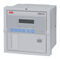
Motor Protection Relay
Technical Reference Manual - ANSI Version
REM 610REM 610
1MRS755537

 Loading...