4.2.3.4 Operation principle
The function can be enabled and disabled with the Operation setting. The
corresponding parameter values are "On" and "Off".
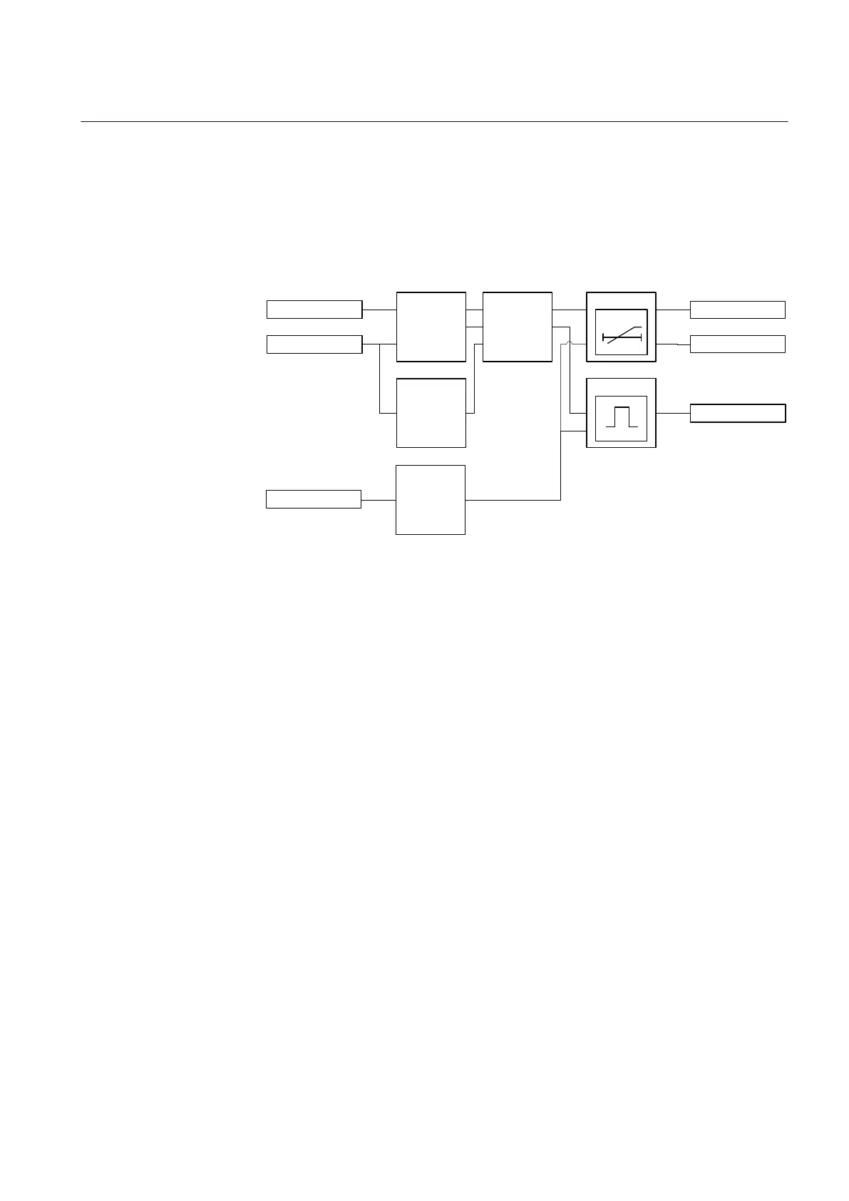
The operation of transient/intermittent earth-fault protection can be described with
a module diagram. All the modules in the diagram are explained in the next sections.
BLK_EF
OPERATE
Io
Uo
BLOCK
START
Timer 2
t
Timer 1
Transient
detector
Fault
indication
logic
Level
detector
Blocking
logic
A070661 V4 EN
Figure 152: Functional module diagram. Io and Uo stand for residual current
and residual voltage
Level detector
The Level detector module compares the measured residual voltage to the set
Voltage start value. If the measured value exceeds the set Voltage start value, the
module reports the exceeding of the value to the Fault indication logic.
Transient detector
The Transient detector module is used for detecting transients in the residual
current and residual voltage signals.
The sensitivity of the transient detection can be adjusted with the Min operate
current setting. This setting should be set based on the value of the parallel resistor
of the coil, with security margin. For example, if the resistive current of the parallel
resistor is 10 A, then a value of 0.7*10 A = 7 A could be used. The same setting is
also applicable in case the coil is disconnected and the network becomes unearthed.
Generally, a smaller value should be used and it must never exceed the value of the
parallel resistor in order to allow operation of the faulted feeder.
Fault indication logic
Depending on the set Operation mode, INTRPTEF has two independent modes for
detecting earth faults. The "Transient EF" mode is intended to detect all kinds of
1YHT530004D05 D Section 4
Protection functions
615 series 305
Technical Manual