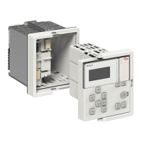
3. Loosen the fixing screw of the SPACOM relay to temporarily mount installation
support frame by using the holes on the frame.
Aften inserting the installation support frame, tighten the fixing screws again.
Figure 6: Temporary mounting of the installation support frame to the SPACOM
relay
The retrofit connectors are marked on the top based on the existing SPACOM
relay terminal numbers. This enables the user to disconnect secondary wires
from the existing SPACOM relay terminal and re-connect the wire on the
corresponding number of the retrofit connectors. Retrofit connectors are
closed at the time of delivery and need to be opened before wires can be
inserted.
Re-wiring for the X100, X110 and X130 connectors will be permanent, but
separate push-in type terminals are provided for instrument transformers (CTs
and VTs) secondary wires temporary connection.
4TLB000504 A
Mounting
Installation Manual
21