Do you have a question about the ABB REX610 and is the answer not in the manual?
Describes the purpose and content of the operation manual for the REX610 protection relay.
Identifies the intended users of this manual, requiring basic knowledge of protection equipment.
Provides a link to access the latest documents from the ABB website.
Details the product's design considerations for sustainability, including compliance with RoHS directives.
Provides guidance on recycling and proper disposal of the protection relay and its components.
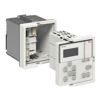
Describes the REX610 as a configurable all-in-one protection relay for power distribution applications.
Records the product version history, starting with version 1.0.
Introduces the Local Human-Machine Interface (LHMI) and details its display capabilities.
Explains the function of the Ready, Start, and Trip LEDs, and the icon area for user level and action status.
Describes the keypad layout and the function of each push button for navigation and control.
Groups object control, navigation buttons, and command buttons for LHMI interaction.
Explains the meaning of the Ready, Start, and Trip LEDs for indicating protection status and alarms.
Describes how to read and write numerical, string, and enumerated parameter values using the LHMI.
Details the functionality of the USB front port for communication and power-up.
Outlines the predefined user accounts (VIEWER, OPERATOR, ENGINEER, ADMINISTRATOR) and their access rights.
Details default user roles, rights mapping, and how user authorization is enabled on the LHMI.
Explains the audit trail for logging system activities and security-related events for administrators.
Describes communication protocols like IEC 61850 and Modbus used for station communication.
Introduces PCM600 as the tool for managing all stages of the protection relay's lifecycle.
Explains connectivity packages and specifies required versions for PCM600.
Describes the concept of modification support for delivered relays, including hardware module additions.
Details the procedure for logging into the LHMI, including enabling password authorization.
Explains how to manually log out from the LHMI and the automatic logout procedure.
Covers turning on the display backlight and identifying the device via the Information menu.
Explains how to identify the IEC 61850 edition (1 or 2) supported by the relay.
Describes how to identify the relay's composition code based on its hardware modules.
Details the process of configuring the SD card, including formatting requirements for disturbance records.
Groups adjusting display contrast and changing local HMI language.
Explains how to switch between different display symbol conventions (IEC 61850, IEC 60617, IEC-ANSI).
Groups navigating LHMI menus and understanding the menu structure.
Explains how to scroll through menu items and parameter values when they exceed display capacity.
Groups changing the default view and browsing setting values.
Explains how to edit parameter values, including factors affecting parameter visibility and the need to commit settings.
Guides on editing numerical parameter values, including increasing/decreasing digits and setting min/max values.
Groups editing string and enumerated parameter values.
Describes how to save edited values to RAM or non-volatile memory, and the effects of committing or cancelling.
Explains how to use the Clear button to reset messages, indications, and recordings.
Details how to clear indications, LEDs, and events using the Clear view and shortcuts.
Covers basic operations during normal protection relay use, including monitoring and checking procedures.
Explains how to identify disturbances using indicator LEDs (Ready, Start, Trip) and further actions.
Groups disturbance recording triggering, analysis, and report generation.
Details how the relay monitors its internal status, including hardware, software, and communication errors.
Covers setting protection relay parameters via LHMI or PCM600, and the need for verification.
Groups editing function settings and defining values for different operating conditions.
Explains how to monitor the protection relay's operation via LHMI indications like LEDs and display messages.
Describes how indication and tripping messages are displayed and how to close them.
Explains how to monitor internal relay faults, indicated by the flashing green Ready LED and messages.
Guides on accessing condition monitoring data via the LHMI.
Explains how to view momentary actual values for power system measurements on the LHMI.
Lists and describes example measured values accessible via the LHMI, such as currents and voltages.
Details how to monitor measured and calculated values using the LHMI measurements menu.
Introduces the functionality for collecting and analyzing recorded data for post-fault analysis.
Groups creating/monitoring disturbance recordings and monitoring events.
Groups remote monitoring capabilities and SD card memory monitoring.
Describes how to monitor SD card memory for sufficient space for disturbance record copying.
Explains how to control primary equipment like circuit breakers via the LHMI in local-control mode.
Details the procedure for opening and closing objects using the LHMI's control menu and authorization.
Describes how to set up and use a closing delay for operations performed from the LHMI.
Explains how to clear and acknowledge messages, indications, and events using the Clear button.
Details the clearing and acknowledgment functions available through the LHMI's Clear view.
Covers changing the relay's functionality by defining and activating setting groups.
Explains how protection relay settings are planned for different operation conditions using setting groups.
Details the procedure for selecting and activating a specific setting group on the relay.
Describes how to copy settings from one group to another or to all available groups.
Guides on how to browse, select, and edit values within specific setting groups.
Details how to browse and edit individual parameters within a selected setting group.
Explains how to select and change the mode for programmable LEDs on the LHMI.
Describes how to set the delay for autoscrolling measurements view when the user is logged out.
Provides steps for tracing and identifying hardware, runtime, and communication errors.
Guides on checking modules, supervision events, and visual inspection for hardware faults.
Groups identifying runtime errors and communication errors.
Details how to verify the front communication link operation by checking LEDs.
Groups checking time synchronization and running the display test.
Explains the self-supervision system that monitors software, hardware, and external circuits for faults.
Details how internal faults are indicated, disabling protection operation and activating the Ready LED.
Explains the fault code format and lists common internal fault indications and their categories.
Describes warning indications, their format, and how they are displayed on the LHMI.
Lists warning indications, their categories, and additional information for troubleshooting.
Details the steps to reboot the protection relay's software via the LHMI.
Groups restoring factory settings and setting/managing passwords.
Offers checks for identifying problems related to functions, blocking, mode, and measurement values.
Guides on physically inspecting wiring for correct connections and polarity, especially for current and voltage transformers.
Explains how corrupted or faulty measurement data can halt operation and the need to check the measurement chain.
Lists essential steps and preparations before starting the commissioning work for the protection relay.
Covers familiarization with drawings, software compatibility, settings documentation, and test equipment.
Focuses on verifying the power supply and polarity before powering up the protection relay.
Groups recommended tests for CT circuits and VT circuits.
Guides on checking connected signals for binary input and output circuits, ensuring they meet specifications.
Explains user categories, default passwords, and password policies for LHMI authorization.
Covers establishing communication between PCM600 and the protection relay via Ethernet or USB.
Details connection variants and requirements for communication between PCM600 and the relay.
Groups setting IP addresses for Ethernet and general communication settings.
Groups serial port parameters and serial link diagnostics/monitoring.
Guides on configuring Ethernet port settings via PCM600 for consistent configuration export.
Details how to define serial port settings, including mode, baud rate, parity, and delays.
Explains how to change protocol-specific settings like port, address, and link mode.
Refers to the technical manual for details on connecting jumper connectors.
Groups changing language, adjusting contrast, symbols, and default view.
Groups setting system time, synchronization, and DST parameters.
Groups DST parameters and defining setting groups for relay configuration.
Groups selecting a setting group for editing and browsing/editing its values.
Describes how to activate a specific setting group for the protection relay's operation.
Provides detailed guidance on setting parameters, including documenting changes and using PCM600.
Groups defining disturbance recorder channel settings and configuring analog inputs.
Covers essential tests before activating digital outputs, including changing control authority.
Details how to set control authority to 'Local' to enable LHMI test mode changes.
Explains how to activate the test mode via LHMI, indicated by a flashing green Ready LED.
Guides on selecting test mode status (Normal, Internal fault, Test off) and confirming the selection.
Describes how to activate or deactivate digital outputs for testing purposes.
Explains how to activate or deactivate output signals for protection and other functions for testing.
Details how to test the internal fault scenario using LHMI, activating the fault output contact.
Explains how to activate IED blocked or test and blocked modes, indicated by flashing LEDs.
Guides on selecting test mode status for IED blocked or test and blocked modes and confirming.
Explains the feature for tracing composition changes in relay SW or HW for better support and maintenance.
Defines Human-Machine Interface (HMI) and Local Human-Machine Interface (LHMI).
Defines IEC 61850 standard and Ethernet protocol.
Defines IED, PCM600, CT, and VT.
| Type | Protection relay |
|---|---|
| Frequency | 50/60 Hz |
| Housing | Plastic |
| Communication Protocols | IEC 61850, Modbus, DNP3 |
| Number of Outputs | Up to 8 |
| Mounting | DIN rail |
| Protection Functions | Overcurrent, earth fault, thermal overload, under/over voltage, frequency protection |
| Enclosure | IP20 |
| Number of Inputs | Up to 16 binary inputs |