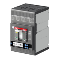
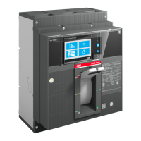
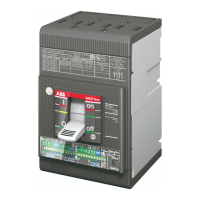
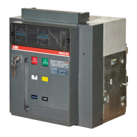
ABB | SACE Tmax XT
170 | © 2019 ABB | 1SDH002039A1002 - ECN000093027 - Rev. A External accessories | 15 - Ekip Signalling 3T
Interface
Five signalling leds are available:
Figure 54
LEDs Description
Power
Signals the on state and correct communication with the trip unit:
• off: module off
• on steady or flashing synchronized with the trip unit Power led: module on and
communication with trip unit present
• flashing not synchronized with trip unit Power led (two fast flashes per second):
module on and communication with trip unit absent
I 41, I 42, I 43, I 44
Indicate the state of the input contacts:
• off: input disabled
• on steady: input enabled, sensor connected and measurement valid
• flashing: input enabled, sensor not connected and/or measurement not valid
Access from the display
The following areas are activated on Ekip Touch if the Ekip Signalling 3T module is detected correctly:
• Measurements page, accessible from the Home page, containing the measurements of all the PT1000
and 4-20mA Current Loop inputs of both modules 3T-1 and 3T-2
• information submenus in the About-Modules menu containing: serial number, module version and statuses
of sensors (Present/Alarm)
IMPORTANT:
• if one or more sensors are in the alarm status, the signal on the diagnosis bar will be:
Ekip Signalling 3T
• if a sensor is not enabled, the status indicated is: Present
Remote configurations
The configuration of the module is available:
• via Ekip Connect, with communication accessories via service connector or with communication via
system bus
• via own communication system and Ekip Com modules installed on circuit-breaker, in the conditions
required by the trip unit (use System Interface for details)
All the measurements, states and alarms of the module are available in both conditions.
NOTE: parameters and measurements are distributed in Ekip Connect pages and communication
addresses sometimes nonsequential; references to the pages in Ekip Connect 2 are given in
the tables below
Enabling and measurements
The individual inputs of the modulecan be enabled in the Ekip Signalling 3T page: I42 Temperatures, I43
Temperatures, I44 Temperatures, I41 Current 4-20mA (per 3T-1), I52 Temperatures, I53 Temperatures, I54
temperatures, I51 Current 4-20mA (for 3T-2).
Parameter Description Default
Enable
Enables the specific input and relative alarm state and signaling
controls to be activated
Enabled
 Loading...

